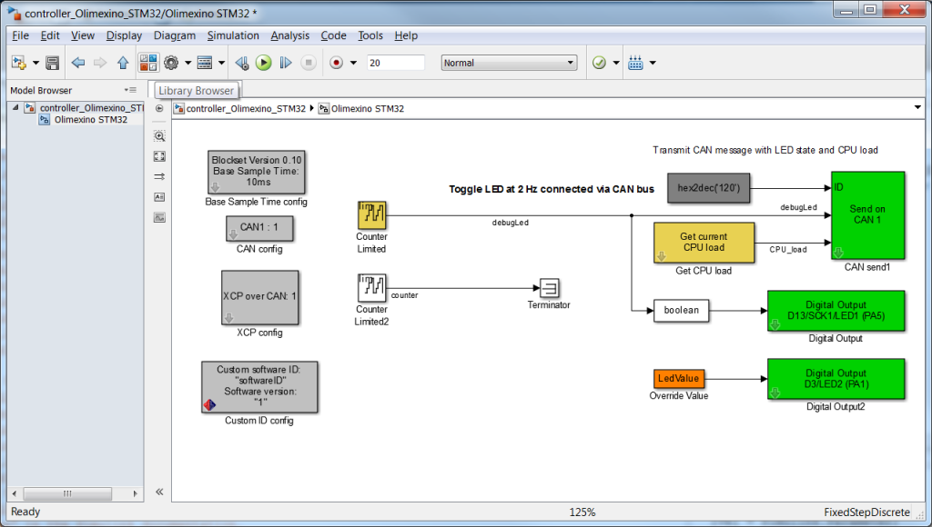
Adding the blocks to control the motor
To add a block for the Olimexino click on the ‘Library browser’ button in the toolbar of the model:
The library will be opened. For block for the Olimexino open the ‘HANcoder STM32 Target’ in the list of libraries on the left of the screen by double clicking on it. After this open ‘Olimexino STM32’ and go to Analog Inputs’.
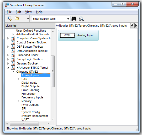
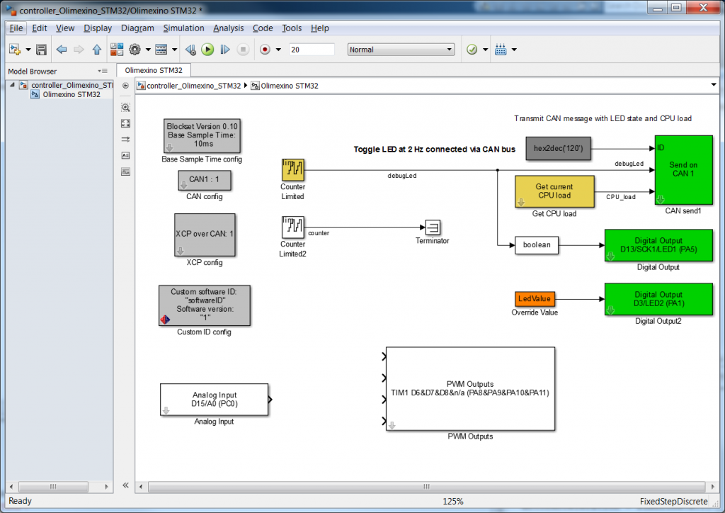
Click and hold the block called ‘Analog Input’ and drag it into the model. Now go to ‘PWM Outputs’ in the library and do the same for the ‘PWM outputs’ block. You should end up with the following model:
First we will set up the blocks for the right pin on the Olimexino. We start with the settings of the analog input. Open the settings dialog by double clicking on the block and select pin: ‘Connector 2 – D18/A3(PORTC PIN3) from the dropdown menu.
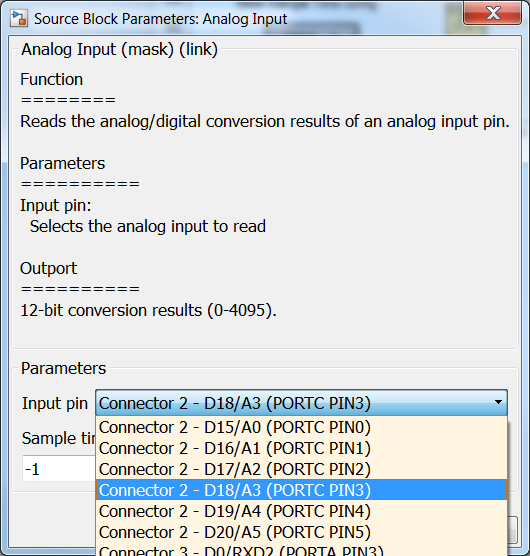
It is not necessary to change the sample time. Note that the output is 0-4095. Save the settings by clicking ‘OK’.
Next up is the PWM Outputs block, double click the block to adapt the settings. When you scroll down you will see the following screen:
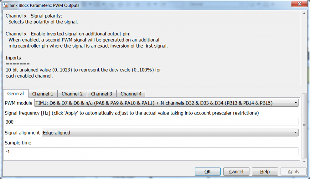
Note that the input is 0-1023.
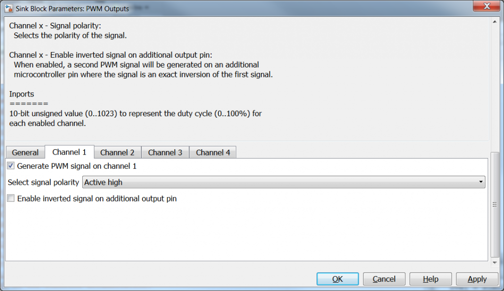
The Ardumoto is connected to pin D3 on the Olimexino so we have to choose ‘TIM2: D2 & D3 & D1 & D0(PA0 & PA1 & PA2 & PA3)’ In order to turn off the other PWM signals generated on the other pins go to the tab of Channel 1,3,4 and deselect: ‘Generate PWM signal on channel x’ This is done to delete the other inputs of the PWM outputs block so Simulink will not give a warning.
Further we have to select a frequency for the PWM signal to drive the motor, a recommended frequency would be 10000Hz.Go back to the ‘General’ tab and replace 300 by 10000. Close the dialog by clicking OK.
Next we will connect the two block with eachother, however we have seen that the Analog input has a range of 0-4095 (0 to 3,3V) and the PWM output has a range of 0-1023 (0-100%). The value of the analog input is 4 times higher than the input necessary for the PWM Output. Therefor we need to add a gain block, this can be found in the Simulink library under Simulink -> Math Operations. Open the library as previously described and find the ‘Gain’ block and drag it into the model. Put it between the Analog Input block and the PWM Outputs block and connect the blocks by clicking and holding the left mouse button and drag the output of one block to the input of the other block. If the blocks are not properly connected the line will be red, the line becomes black when the blocks are properly connected.
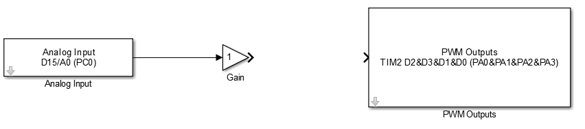
When the blocks are connected double click the gain and enter the value 0.25 for Gain. Go to the Signal Attributes tab and change the Output data type: from ‘Inherit: Inherit via internal rule’ to ‘uint16’. Close the dialog by clicking OK. When the output data type is set to ‘Inherit: Inherit via internal rule’ Simulink will choose calculate the appropriate data type itself. Because a fraction is used, Simulink will most probably use a fixed point data type. The input of the PWM Outputs block however needs to be an unsigned 16 bit integer(uint16), therefore we choose this manually.
Important: Note that the Digital Output D3 is also connected to the LED, it is therefore necessary to delete the ‘LedValue’ and ‘Digital Output D3/LED2 (PA1)’ blocks.
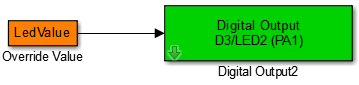
Delete these!
We are now ready to generate the code and test the program on the Olimexino.
To start the code generation click the ‘Build model’ button in the toolbar of the model or press ctrl+b.

Delete these!
We are now ready to generate the code and test the program on the Olimexino.
To start the code generation click the ‘Build model’ button in the toolbar of the model or press ctrl+b.