HANcoder/Training Material/AutomaticLightControlSystem/5
LED Control System Part 5
Part 5: Adding an output to the model
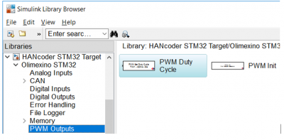
In this part of the tutorial an output will be added to the model. In this tutorial we will use an LED for the output. To be able to dim the LED, rather than just turning it on and off, a PWM signal is used. To generate a PWM output signal, some function blocks need to be added. The first block is being used to configure the PWM signal and the second block is being used to generate a PWM signal on a specific output pin. Open the Library Browser in Simulink. Within the library browser, navigate to HANcoder STM32 Target => Olimexino STM32 => PWM Outputs. On the right side of the library browser, you’ll find two blocks: PWM Duty Cycle and PWM Init.
Figure 17 Library Browser PWM Output
Drag both blocks into your model. Double click the PWM Init block to configure the PWM module.
The LED is connected to output D0. This output can also be used as a communication data line. In that case it’s the RX line. On the sensor shield the fifth large pin should be labeled: RX and TX. By connecting the LED to this pin, the intensity of the LED can be changed when a PWM signal is provided to pin D0.
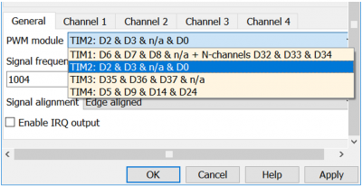
Select the correct PWM module that contains pin D0.
Figure 18 PWM Module selection
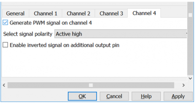
Now, the PWM module has been configured. Now you only need to select the correct channel to send the PWM signal to. The PWM module you'll need to select is: TIM2: D2 & D3 & n/a & D0. If you want to generate a PWM signal on D2, you would have to activate Channel 1. For D3, you would have to activate Channel 2 etc. Because you need to generate a signal on pin D0, you need to activate Channel 4. So go to the Channel 4 tab and select the box that says "Generate PWM signal on channel 4".
Figure 19 PWM channel selection
Click OK to apply the changes.
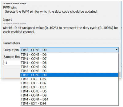
Now everything has been configured properly so that a PWM signal can be generated using the PWM Duty Cycle block. Open the configuration of this block by double clicking it. Select the correct Output pin and press OK.
Figure 20 PWM port selection
To make the output of the PWM signal adjustable in HANtune, an adjustable HANtune parameter needs to be created. The model sees a parameter as a constant value. HANtune is able to hook into this constant value and change it. Because it is seen as a constant value, you’ll need to add a Constant parameter to the model. Open the Library Browser in Simulink and drag a Constant block into the model. The Constant block is a commonly used block and can be found under Simulink => Commonly Used Blocks. Connect the output of the Constant block to the input of the PWM block.
Figure 21 Library Browser Constant
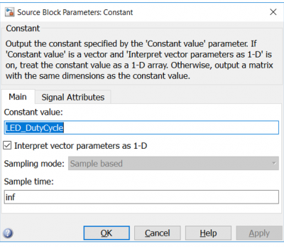
Now, open the block by double clicking it and name the parameter Constant Value to something logical. In this example, we’ll use the name “LED_DutyCycle” for this parameter. The name that you gave this parameter should now appear in HANtune. It is useful to know what the function of this parameter is.
Figure 22 Constant Block value
This parameter is able to send out an integer, which is being used to send a PWM signal that changes the LED’s intensity from 0% to 100%. The PWM block requires a 10 bit signal, so a signal that goes from 0 to 1023. It converts this signal to a duty cycle of 0% to 100%. This information is also described in the PWM block.
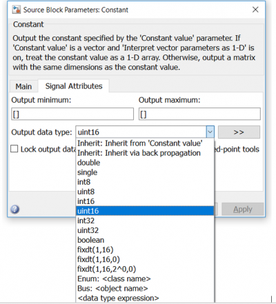
Because the PWM needs an integer of 0 to 1023, you’ll need to determine which data type needs to be sent to from the Constant block to the PWM block. By changing the Output data type to uint16, we can send the correct data type to the PWM block. Uint16, an abbreviation for "unsigned integer 16 bit", the datatype can contain a 16 bit positive integer.
Figure 23 Constant Block output data type
Build your model. Simulink will ask which number you want your constant to be by default. By default, Simulink will give it a value of 0. Click OK and wait for Microboot to load up flash the program to the Olimexino.
Because changes have been made to the program in the microcontroller, you’ll need to unload and reload the ASAP2 file in HANtune. Double click the ASAP2 file to unload it, then double click it again to load the updated version.
Now, go to ASAP2 elements, where you’ll see that the parameter LED_DutyCycle has been added to the list of parameters. Drag the parameter LED_DutyCycle onto your dashboard and make it a SliderEditor. Change the range of the SliderEditor to the same maximum resolution as that of the PWM block. (1023)
Connect het Olimexino by pressing (F5) and change the intensity of the LED with the slider in HANtune. Make sure to move the slider itself, which is positioned on the right side of the SliderEditor block.
