OpenLoopBuild
Open Loop control
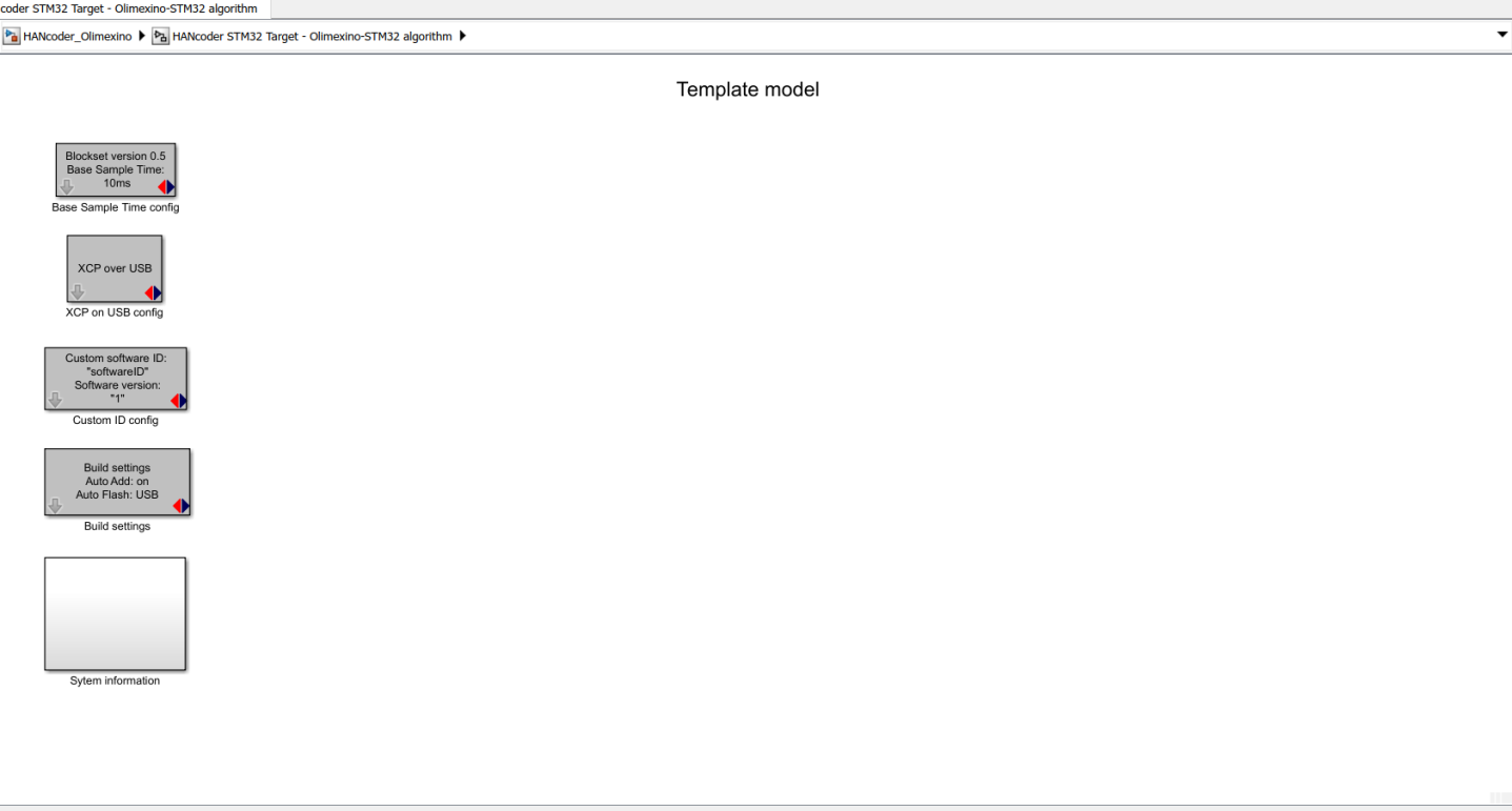
An open loop control system is a control system that doesn’t use any feedback. It is the simplest type of control system, with the downside of it being fairly crude. It can’t be used for every system though. Nonlinear systems or unpredictable systems in particular are hard to control with this control scheme. The first part of this practical assignment will be to make an open loop control system to control an automotive throttle body. You will have to send out a PWM signal to the throttle body that is relative to the throttle position (potentiometer). Open MATLAB Simulink® and run the HANcoder_Olimexino.slx template model that you can find in you HANcoder Target directory. Double click the picture of the Olimexino board to enter the model. Then delete the “Inputs”, “Algorithm”, and “Outputs” blocks, so you’ll have a nice and clean model to start off with. Your model should look now a little something like this:
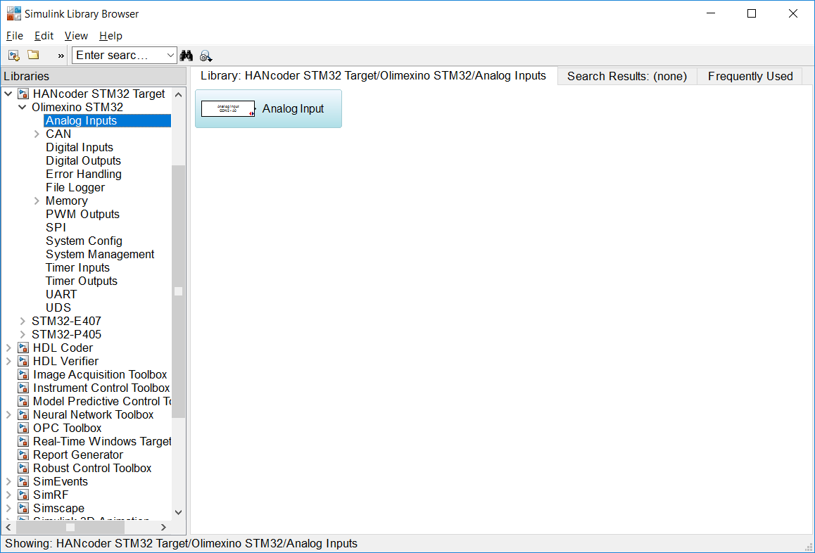
First, you’ll need to add an input to the model, which in this case will be the potentiometer representing the throttle. From the Library Browser, you’ll need to drag an analog input block into the Simulink model and, under properties, select the input connector that the potentiometer is connected to, A0 in this case. Open Simulink, click “Library Browser” and navigate to HANcoder STM32 Target -> Olimexino STM32 -> Analog Inputs. In the right column, the Analog Input block will appear. Select the block and drag it into the template model.
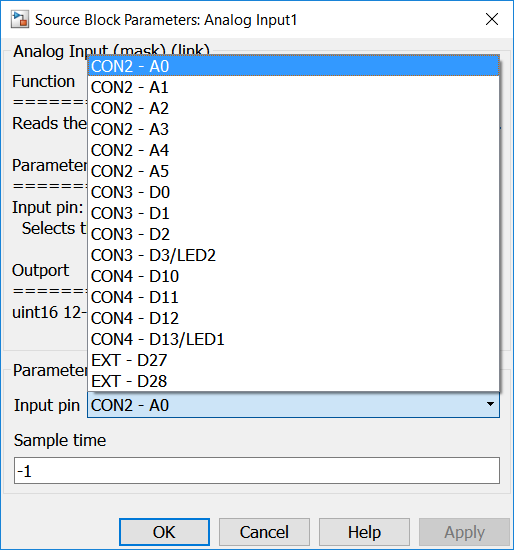
Configure the Analog Input block to read the Input pin A0 by double clicking it. The output of this block needs to be configured to become available in HANtune.
Now an output needs to be added to the model. Because the throttle body is the thing that needs to be controlled, an output is needed that can control the throttle body. Because a microcontroller isn’t able to meet the throttle body’s power requirements, some interface circuitry in the form of an H-bridge is required as an intermediary between the microcontroller and the throttle body. This H-bridge can send out a 0-12v PWM signal in two directions to regulate the speed, direction of movement and position of the throttle valve. The H-bridge operates using two logic level PWM inputs, one to control the movement of the valve clockwise and the other to control the movement of the valve counter-clockwise. You can use the Olimexino microcontroller to send out a 0-3.3v PWM signal to these PWM inputs. Because the H-bridge uses one PWM signal for each direction, you’ll need to use two PWM output in your model, if you want to operate the throttle bi-directionally.
Q: Which input pin is the potentiometer connected to?
Q: How can you control throttle body that works with a 12v PWM signal with a microcontroller that sends out a 3.3v PWM signal?
With this first assignment though, you will only be driving the electric motor in one direction to open the throttle. The spring that’s built in to the throttle body will be used to close the throttle valve. To open the throttle valve, the PWMA pin on the H-bridge needs to get a PWM signal from the Olimexino microcontroller. This PWMA pin of the H-bridge is connected to the digital output D0 of your Olimexino board. Along with the PWM output block, a PWM Init block needs to be added.
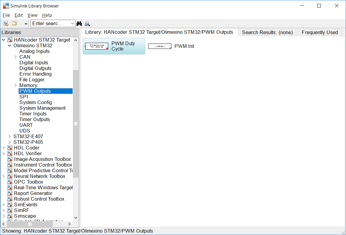
Open the Library Browser in Simulink. Navigate to HANcoder STM32 Target Olimexino STM32 PWM Outputs. On the right side of the library browser, you’ll find two blocks: PWM Duty Cyble and PWM Init.
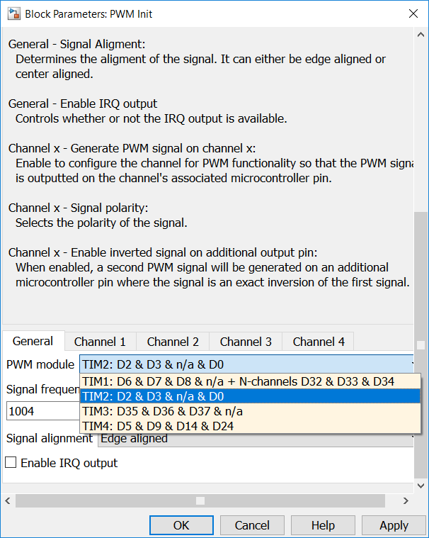
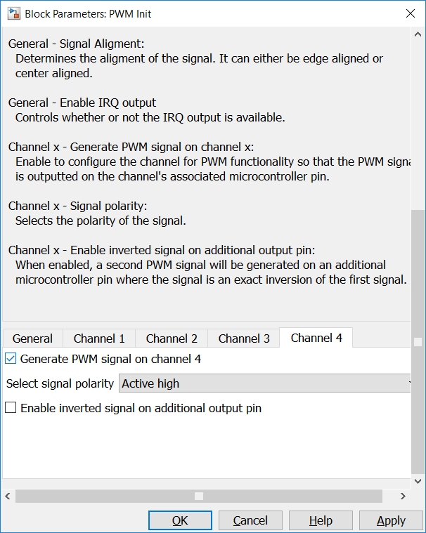
Drag both blocks into your model. Double click the PWM init block and select a switching frequency of 1 kHz, which MATLAB® will change to 1004Hz. Also select the PWM module with the correct digital output pins and send out a PWM signal on these pins, in this case the PWM module that contains D0 and D3. Because the PWM module “TIM2: D2 & D3 & n/a & D0” is being used, Channel 1 will be D2, Channel 2 D3, Channel 3 not available, and Channel 4 D0. Because the opening action of the throttle valve is connected to pin D0, a PWM signal needs to be created on D0. Click the Channel 4 tab and check the checkbox that says “Generate PWM signal on channel 4”.
Now double click the PWM duty cycle block and select the correct output pin.
Q: Which digital output pins do you need to send the PWM signal to?
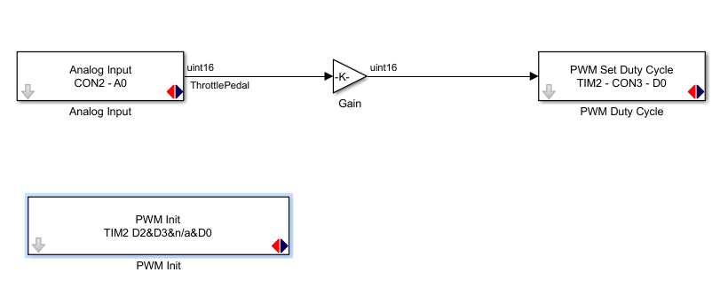
The input and output can now be connected to make a very simple throttle controller that sends out a PWM signal to the throttle valve that is relative to the input signal. However, because the Analog input operates with a 12 bit resolution (0-4095) and the PWM outputs operate with a 10 bit resolution (0-1023), a gain needs to be added to make full use of the potentiometer’s range. Drag a Gain block, from the Simulink Library Browser’s Math Operations category, into your model and put it in-between the analog input and a PWM output. Connect the parts and select the appropriate gain value. Don’t forget to select the correct output data type for the Gain block. The correct datatype, uint16, can be selected by double clicking the gain block.
Q: What gain value needs to be added? It can be very useful to be able to have the ability to view the signal of the throttle pedal (potentiometer) in HANtune. For this purpose, it has to be available as a signal within HANtune. The first thing you’ll need to do, is naming the signal logically. To name the signal, double click the line that runs between the Analog input block and the Gain block. A text box should appear beneath the line. Name it sensibly, you may call it ThrottlePedal for example. Now that the inputs and outputs are assigned, and a gain has been added to make the inputs compatible with the outputs, the model can be uploaded to the Olimexino. The Simulink model is now ready to compile and be programmed to the Olimexino. Build your model.
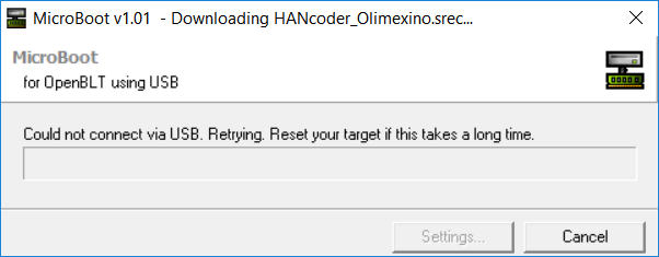
After agreeing to a licensing notification, MATLAB® will call up the GNU ARM Toolchain to convert your model to machine code. After the S file is ready, MATLAB® will start the Microboot program to flash the code to the Olimexino. A similar window to that of Figure 10 should pop up. Reset your Olimexino to flash the program.
