ClosedLoopBuild
Closed loop control
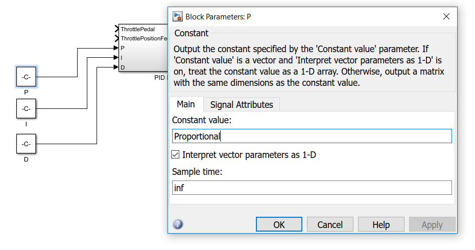
In contrary to an open loop system, a closed loop control system is a type of control system that does use feedback from the system to regulate the output. This works great for systems that are nonlinear or unpredictable. As you would have observed in the first part of the assignment, the throttle valve can’t be operated properly with an open loop control system. This is because the duty cycle and the throttle pedal position aren’t proportional to each other. To counteract this problem, the duty cycle of the PWM signal needs to be regulated based on positional feedback from the throttle valve. A system that uses feedback on the output to regulate, is called a closed loop system. For the next assignment you’ll put together a closed loop system to control the throttle position. Because you want to use a feedback based control system, you can’t just connect the input to the outputs. Here is where a proportional regulation (P-regulation) scheme comes into play. A P-controller bases its output on the difference between a desired value (user input) and a feedback value from the output (feedback input). As the difference between the desired value and the output value is greater, a P-controller will compensate by a larger amount. For this assignment you can use the PID H-bridge controller block to setup a P-regulation scheme. Open the “ThrottlebodyClosed” Simulink model that’s been provided by your teacher and add constant blocks, from the Simulink Library Browser’s Commonly Used Blocks category, to the P, the I and the D inputs of the PID H-bridge controller. You want to be able to adjust these P, I and D values within HANtune to tune the way the throttle body responds to the potentiometer. To be able to adjust these values in HANtune, you’ll need to change the constant value of these blocks to a logical name. Double click the each blocks and enter a logical name in the “Constant value” field. You may call the block connected to the P input “Proportional”, the one connected to the I input “Integral” and the one connected to the D input “Derivative”, for example. Or you could just simply call them “P”, “I” and “D”. Just name them logically so you’ll know which parameter does what, when you enter HANtune. Set the data type of these constant blocks to “Double”. Unlike Uint16, which only supports integer values, the data type Double supports decimal figures.
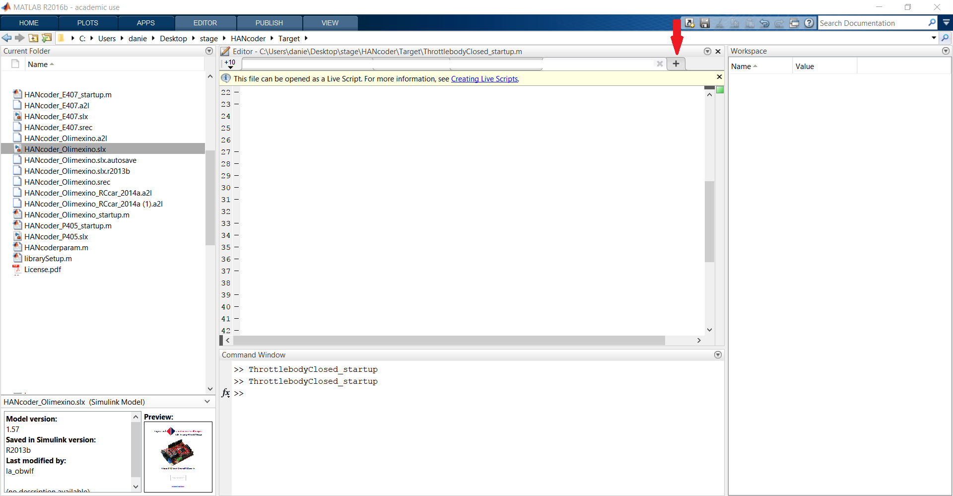
However, these parameters aren’t linked to HANtune yet. They have to be set up to be Simulink parameters before they will be adjustable in HANtune. Open up MATLAB® and make a new script by pressing the + symbol.
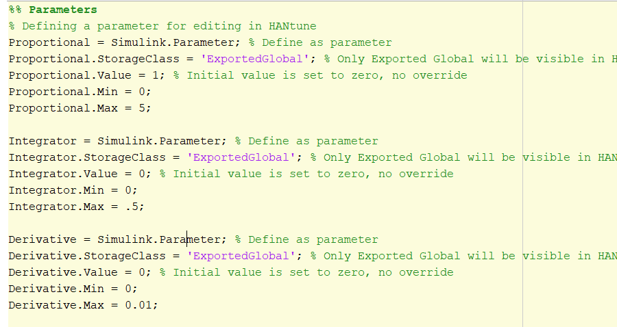
Make sure to remember the names of the constant values for the next step. In the script write:
{NameOfConstantValue} = Simulink.Parameter;
This will define the constant value as a Simulink parameter.
{NameOfConstantValue}.StorageClass = ‘ExportedGlobal’;
By defining it as an ‘ExportedGlobal’, HANtune will be able to see the parameter.
{NameOfConstantValue}.Value = 5;
This will set the initial value of the parameter to 5. For the P variable, make this value 5. For the I and the D variable, make sure to leave this value to 0!
{NameOfConstantValue}.Min = 0;
{NameOfConstantValue}.Max = 20;
This will set the minimum and the maximum allowable values.
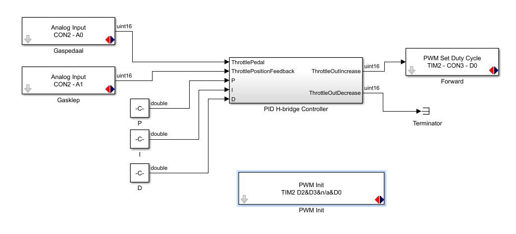
Now press CTRL+S to save the script and name it “ThrottlebodyClosed_startup”. Like last time, the you’ll need to do is to add an input to the model, which in this case will be the potentiometer representing the throttle. Drag an analog input block into the Simulink model and, under properties, select the input that the potentiometer is connected to. But, as this will become a closed loop system, there is also an analog feedback signal that needs to be used as well. For this reason, a second analog input needs to be added to the model. This analog input signal needs to be linked to the analog input pin that the feedback signal is connected to, which, in this case, will be pin A1. The next thing you’ll need to do is connecting both analog input signals to the correct inputs of the PID H-bridge Controller. Connect the analog input of the potentiometer (throttle pedal) to the ThrottlePedal input and connect the analog input of the throttle valve position feedback to the ThrottlePostitionFeedback input. Double click the line that runs from your Analog Input A0 to the ThrottlePedal Input of the PID H-bridge Controller and name it logically. (ThrottleInput for example) Also double click the line that runs from Analog Input A1 to the ThrottlePositionFeedback input of the PID H-bridge Controller and name this signal logically as well. (ThrottleFeedback for example) Now the correct output signals need to be added to the model. Before making a bi-directional operating throttle controller, you’re going to make a single direction operated throttle controller. Drag a PWM Set Duty Cycle block into your model and connect it to the ThrottleOutIncrease output of the PID H-bridge controller. Assign the correct pin number to the PWM Set Duty Cycle. Then drag a terminator into your model and connect it to the ThrottleOutDecrease output to prevent error messages from occurring. Now drag a PWM Init block into the model, select the correct TIM under its properties and generate a PWM signal on the pins accordingly.
Build the program and flash it onto your Olimexino. Keep the power supply turned off.


