ClosedLoopTest
Testing the closed loop control
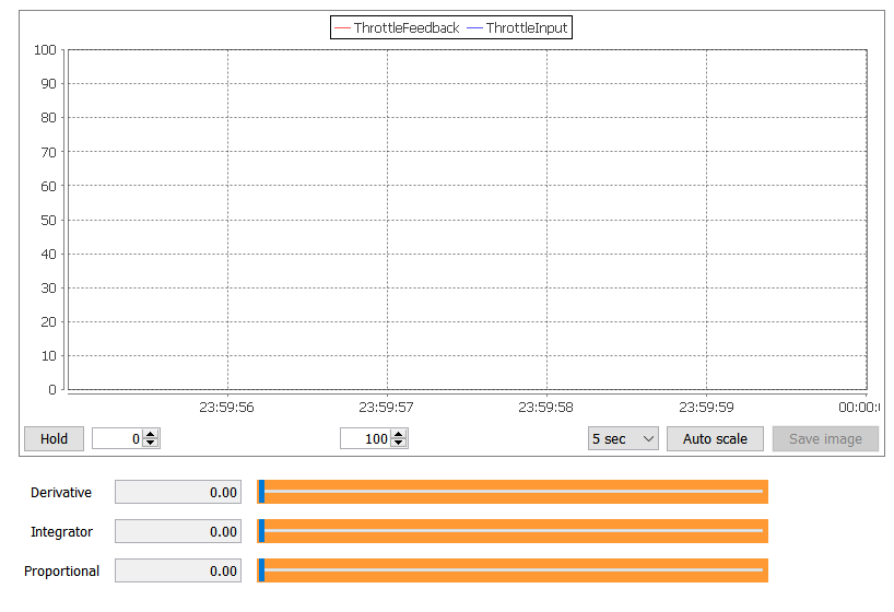
Open HANtune and make a new project. Add and load the ASAP2 file “ThrottlebodyClosed.a2l” file that was created when you built the model. Go to the “ASAP2 elements” tab and drag the P, I and D parameters into the model as slider editors. Also drag the ThrottleFeedback and ThrottleInput signals into the dashboard as a scopeview.
Now press (F5) and connect the Olimexino to HANtune.
Q: Write down the values that HANtune shows for both the minimum potentiometer value, and the value for the positional feedback, when the throttle valve is in its idle position.
Now turn the power supply on and turn the potentiometer until the throttle valve has opened completely. Write down the maximum value of the potentiometer and write down the feedback value of the throttle valve when it’s in its full throttle position. Turn the power supply off again.
| Potentiometer | Minimum value | _______ |
| Maximum value | ||
| Feedback | Value idle throttle position | |
| Value full throttle position |
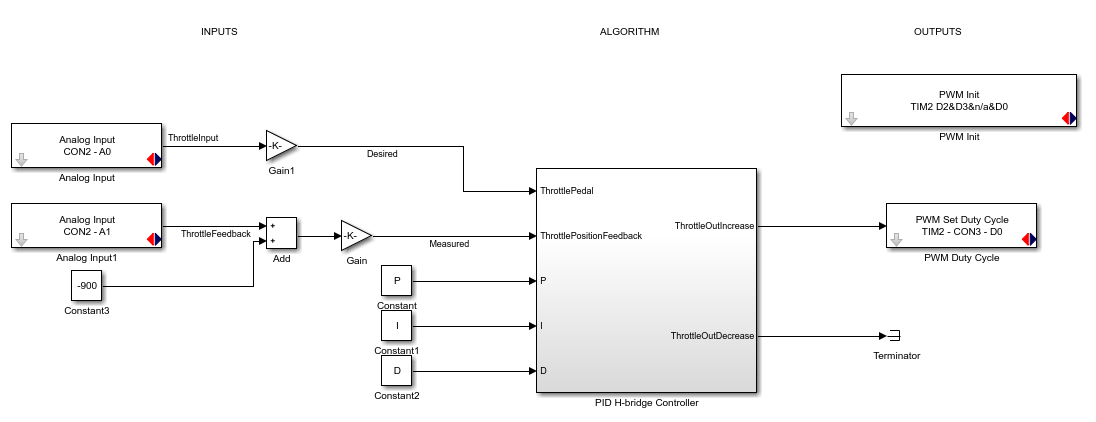
As you can see from the values, the positional feedback has a different operating range than the input of the potentiometer. To compensate for that, an offset and a gain need to be added to the model. The offset value that you’ll need to add to the throttle pedal is equal to the feedback value of the throttle valve in its idling position. After all, when the potentiometer is turned to its minimal value, you’d want the throttle valve to be in its idling position. Add an “Add” block from the Math Operations category in your Simulink Library to your model as well as a Constant block. Place the Add block between Analog Input A1 and the ThrottlePositionFeedback input and connect the lines. Connect the constant block to the second input of the Add block. Then change the constant value to the correct offset value, that you’ve found with HANtune.
Now that an offset has been created, the value of the throttle pedal will match that of the feedback signal while the throttle is in the idling position. However, it won’t match the full throttle position. Because of this, a gain needs to be added. To keep the program nice and clean, it’s sensible to convert the inputs values percentages. This makes it much easier to work with the different inputs. The gain value that needs to be added to get a range from 0 to 100%, can be found using the following formula: Gain = 100 / range = 100 / (maximum value – minimum value)
Q: What’s the gain value for the potentiometer?
Q: What’s the gain value for the position feedback?
Drag a “Gain” block from the Math Operations category in the Simulink Library into your model and double click it to enter the calculated gain value. Place the Gain block between the Analog Input A0 and the Add block. Also place a Gain block in between the Add block and the ThrottlePositionFeedback input of the PID H-bridge Controller. Make sure to name the line to the ThrottlePedal input “Desired” and the line to the ThrottlePositionFeedback input “Measured” by double clicking the lines in question.
Build the model and upload it onto your Olimexino. Then go to HANtune, reload the ASAP2 file under the “Project Data” tab and connect the Olimexino to HANtune by pressing (F5) and clicking “Connect & Request”. Turn on the power supply and see how the throttle controller functions.
Q: How does the controller behave.
Q: What happens when you change the P-value in HANtune?
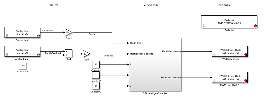
Now the throttle valve needs to be controlled bi-directionally. Delete the terminator and add another PWM Set Duty Cycle to the model. To force the throttle valve to go into the other direction, a PWM signal needs to be put on D3. Connect this PWM output to the ThrottleOutDecrease output of the PID H-bridge controller. Now you have two PWM outputs in your model, one for opening the throttle valve and one for closing the throttle valve. Assign the proper pins to these blocks. Don’t forget to enable this pin in the PWM Init block. The outputs of the PID controller, ThrottleOutIncrease and ThrottleOutDecrease, can now be connected to the PWM out blocks accordingly. The Output of this particular PID controller does already have the correct data type and resolution, so no gain value needs to be added.
Build the program and flash it onto your Olimexino. In HANtune reload the ASAP2 file and connect the Olimexino to HANtune.
Q: How does the controller behave?


