Difference between revisions of "Autodock Model Tutorial"
| Line 28: | Line 28: | ||
=== Plant Model === | === Plant Model === | ||
| − | The Plant Model sub-component, contains the vehicle function. The inputs to the vehicle | + | The Plant Model sub-component, contains the vehicle function. The vehicle function simulates the tractor and trailer for this model. The inputs (tractor velocity and steering angle) are used to calculate the vehicle coordinates and states. Furthermore, some output values are re-used as input values. These values are the 'feed forward' values. The outputs are derivatives, which are looped into the input, integrated, and used to calculate the next iteration of the model. The kinematic equations will not be handled during this tutorial. |
== Animation Model == | == Animation Model == | ||
The final component is the sub-component of the animation model. | The final component is the sub-component of the animation model. | ||
Revision as of 14:34, 16 May 2018
This page is a walk through of the simulation and 3D animation of the Autodocking procedure for a single-articulated vehicle. The page will explain the functionality of the Simulation model and its components, and the connection between the 3D animation model and the simulation results. The result of this walk through is a visually attractive animation in which the 3-dimensional objects (tractor and trailer) visualise the results of the simulation model. The goal of the simulation model is to have the vehicle (truck) follow the reference path, which is an input to the system.
Simulation Model
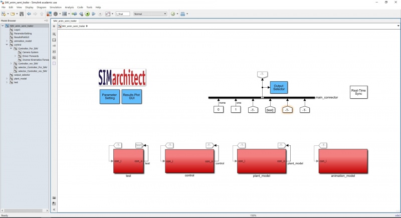
First, open the Simulink model (SAV_anim_semi_trailer.slx). The model will open at the top-layer. The top-layer of the model shows the four main components: Test, Control, Plant Model, and Animation model. The first three are part of the simulation model, and the fourth is the animation model. This can be seen below.
Test
Inside the test sub-component, several parameters are controlled that are specific to this situation. The vehicle follows a pre-defined reference path. Linked to this reference path are the starting point, the switching point from forwards to reverse control, the final location of the vehicle, and the initial conditions of the vehicle. For information about each of the components inside the test sub-component, descriptions have been added to the simulation model. (Double-click on the test block)
Control
Inside the control sub-component, the steering angle required to follow the reference path is calculated. There are two controllers: forwards control and reverse control. As these controllers are nearly exactly the same, only the forwards control will be elaborated. To open the sub-component 'Controller_For_SAV', click the arrow in the bottom-left corner.
Here, there are three areas:
- Semi_pos: This is where the steer-axle and the drive-axle are determined. For forwards are reverse, these are the inverse of each other. The steer-axle (the axle
- Driver Forwards: This is the driver of this model. The inputs are velocity of the trailer, the position of the trailer, and the heading of the trailer. These inputs are then used to calculate the steering angle (at the steer-axle) necessary to keep the rear-axle of the trailer on the reference path. So, the goal of the controller is to let the real-axle of the trailer follow the path.
- Inside the Driver Forwards component (double-click on the grey area), there are two errors defined. The lateral error (distance from the vehicle to the path) and heading error (difference between the reference heading and the vehicle heading). The content of these error calculations will not be handled during this tutorial.
- Inverse Kinematics Forwards: The output from the controller is a steering angle for the rear-axle of the trailer. This axle, however, is not steerable. Therefore, the steering angle must be translated to the front axle of the tractor, which is steerable. The translation is done on the basis of kinematic equations. These equations will not be handled during this tutorial.
The first part of the simulation is in forwards control. Then, after t_for, the steering angle is taken from the reverse controller.
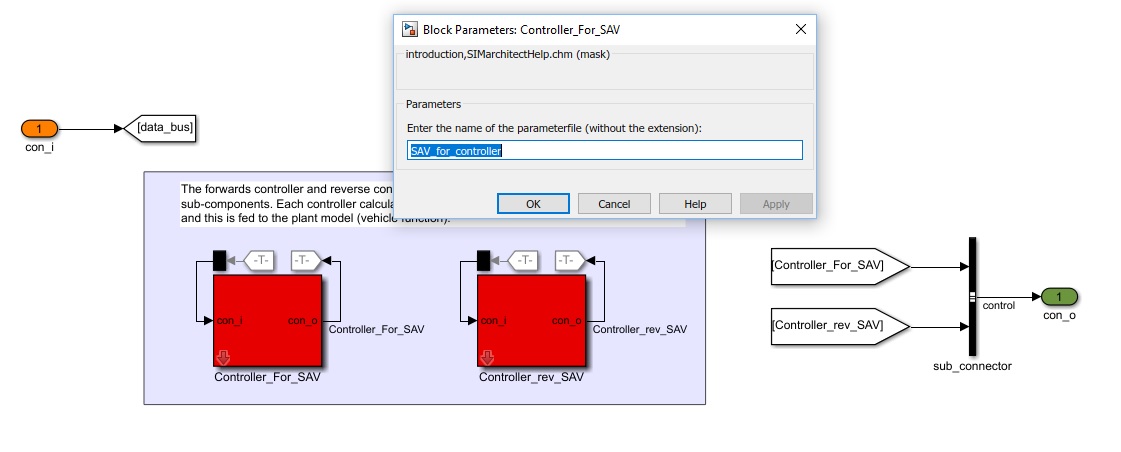
CHECK: Double-click on the Controller_For_SAV. A prompt opens (seen in figure below). Make sure this name of the parameterfile is: 'SAV_for_controller'.
Check this for the Controller_rev_SAV, also. Make sure this name is: 'SAV_rev_controller'. The vehicle function simulates the tractor and trailer for this model. The inputs (tractor velocity and steering angle) are used to calculate the vehicle coordinates and states.
Plant Model
The Plant Model sub-component, contains the vehicle function. The vehicle function simulates the tractor and trailer for this model. The inputs (tractor velocity and steering angle) are used to calculate the vehicle coordinates and states. Furthermore, some output values are re-used as input values. These values are the 'feed forward' values. The outputs are derivatives, which are looped into the input, integrated, and used to calculate the next iteration of the model. The kinematic equations will not be handled during this tutorial.
Animation Model
The final component is the sub-component of the animation model.

