HANcoder/Training Material/AutomaticLightControlSystem
LED Control System part 1
Goal of the tutorial
The goal of this tutorial is to get used to the software tools that are being used to program a microcontroller that works in a model based development environment. Besides experiencing the merits of Matlab Simulink, HANcoder and HANtune, you will learn the meaning of analog voltages with regards to sensors. You will also learn about the use of PWM to regulate the intensity of an LED.
After this tutorial you should be able to:
- Read in analog inputs
- Send out PWM signals
- Visualize signals and parameters within HANtune
- Make a basic control system
Needed tools
You will need a Windows PC with the following software:
- Matlab Simulink 2014a with the correct plug-ins (Getting started guide Olimexino)
- A HANcoder directory Download page
- A HANtune directory (optional: a HANtune.exe shortcut on your desktop) Download page
- GNU ARM Toolchain
- OpenBLT USB driver
- Olimexino STM32 board with a USB bootloader
- USB to mini USB cable
- A sensor shield
- 3 thick cables
- A potentiometer sensor brick
- A LDR sensor brick
- A LED output brick
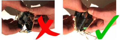
Be careful with the hardware. Make sure that the power adapter and the USB cable are not plugged into the Olimexino when you insert the sensor shield. To prevent bent pins, you will need to make sure to keep the sensor shield straight, when taking it off the Olimexino.
