Difference between revisions of "HANcoder/Training Material/SmartCar"
(→Prototyping board) |
(→e) |
||
| Line 197: | Line 197: | ||
[[File:ProtoBoard.png|1000px]] | [[File:ProtoBoard.png|1000px]] | ||
| − | == | + | == Software == |
== f == | == f == | ||
== g == | == g == | ||
Revision as of 13:07, 11 February 2019
Contents
Introduction
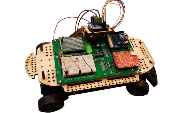
The smart car developed in part by HAN-AR is an all-in-one solution for beginner automotive students. It has built-in support for an OLIMEXINO-STM32, which utilizes a 32-bit microcontroller from STMicroelectronics. additionally, the platform has support for the following modules/features:
- Third party Arduino shields
- Third party motor drivers
- Inertial measurements unit (IMU)
- It has room for implementing your own electronics with a prototyping pcb (5*7cm) & breadboard
- Onboard speed sensor
- LIPO battery with an XT60 connector
- Current measurement functionality (±20A)
- Wireless emergency stop functionality
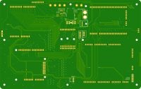
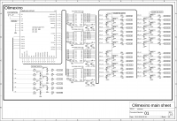
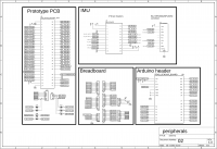
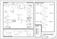
Schematic & Board images
EAGLE files, parts list
Eagle files: File:Eagle Smart Car PCB.zip
Parts list: File:Parts list.zip
Assembly Instructions
How to put the thing together
Mechanical construction
The vehicle’s base frame
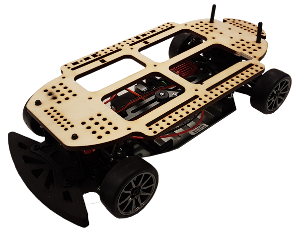
The vehicle consists of a basic frame that is manufactured by a company called “Reely”. This frame is pre-built and consists of the following components:
- The chassis containing
- Transmission
- Drive shaft
- Differential
- Suspension
The frame comes without a motor and wheels. Therefore, these components must also be included in the construction of the vehicle. The wheels and the motor are thus separately ordered. The motor type is a brushed DC motor instead of the brushless alternative. This is because brushless DC motors are easier to drive, as this can be done with an H-bridge circuit. The dimensions of the vehicle are as follows:
- Length : 365mm
- Width : 190mm
- Height : 122mm
- Wheelbase : 260mm
Mounting frame
The mounting frame is the frame on which the electronics can be fastened to. This mounting frame can be fastened to the vehicle via four posts. Under normal circumstances, these posts are used to mount a cover in order to style the vehicle. This is now retrofitted in order to fasten a plate to the vehicle. See the figure below.
The frame is made from 6mm thick birch plywood. Birch plywood has been chosen as the material because of the following reasons:
- It can easily be cut by a laser cutter
- It is cheap and widely available
- It is not brittle compared to other materials such as acrylic
Mainboard funtionalities
Olimexino support
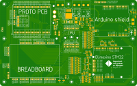
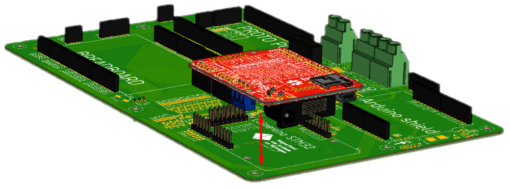
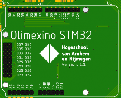
The OLIMEXINO-STM32 is a development board that houses a 32-bit microcontroller within. With the help of the OLIMEXINO-STM32, it is possible to control the vehicle's actions. The vehicle has a mainboard with built-in support for the OLIMEXINO-STM32. The OLIMEXINO can be fitted to a dedicated slot. See figure below.
There are several pins the user has access to when the OLIMEXINO-STM32 is utilized. The pins that are accessible are:
|
Third party Arduino shield support
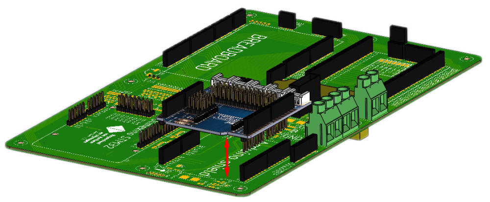
The mainboard on the vehicle has support for Arduino shields. Many different Arduino compatible shields can be fitted onto the mainboard in order to expand the functionality of the vehicle. A dedicated connector has been made to fit this purpose. See figure below.
For more information about third party Arduino shields, click here.
Inertial Measurement Unit
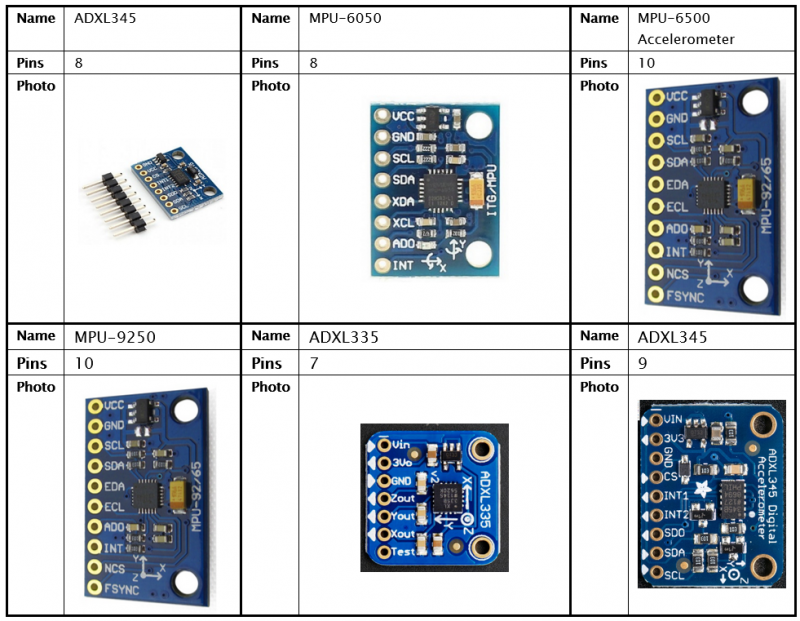
An IMU stands for Inertial Measurement Unit, which can be used for measuring a body’s forces. The mainboard is designed in such a way so that the IMU is interchangeable with other modules in order to keep the system flexible. There are many IMU modules available on the market. A small list of popular IMUs is shown below.
There are many more IMUs then are shown in the table above. Some IMUs have more features such as the ability to measure magnetic fields. Most use different ICs (Integrated Circuits), and depending on the IMU, it would also have a difference in communication protocols. This makes it so that the pinouts and even the physical sizes on many IMUs are different.
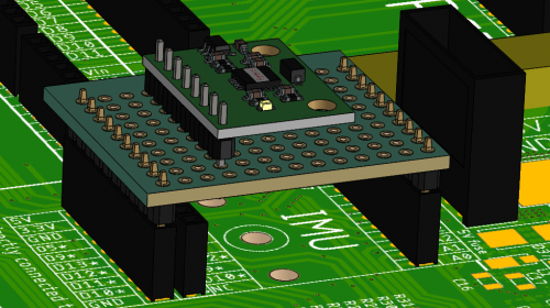
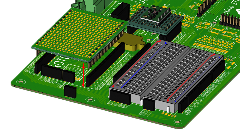
The mainboard has two methods of adding an IMU to the system. Method one consists of using a piece of prototyping board with two 10-pin male headers soldered on each side. The male headers interface with the two outer female headers that are present on the mainboard. By manually connecting each IO to the appropriate connector, it would be possible to connect a host of IMUs to the system. An example of how this would look like is shown in the figure below.
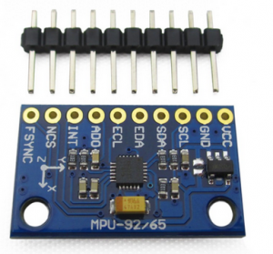
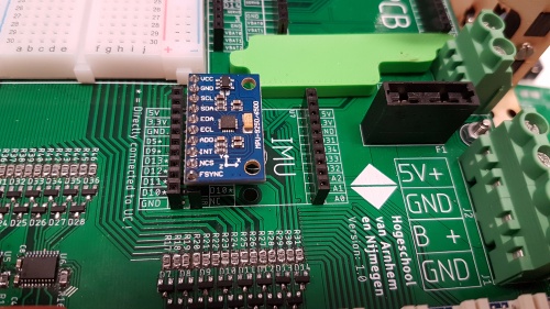
The second way of connecting an IMU to the system is by utilizing the middle connector on the mainboard. The IO on this connector is routed in order to be compatible to one IMU module. This bypasses the need to build a custom arrangement. The IMU module that is compatible is a generic board that uses a MPU-9250 IC. See the figures below for the implementation.
Adding custom electronics
Breadboard
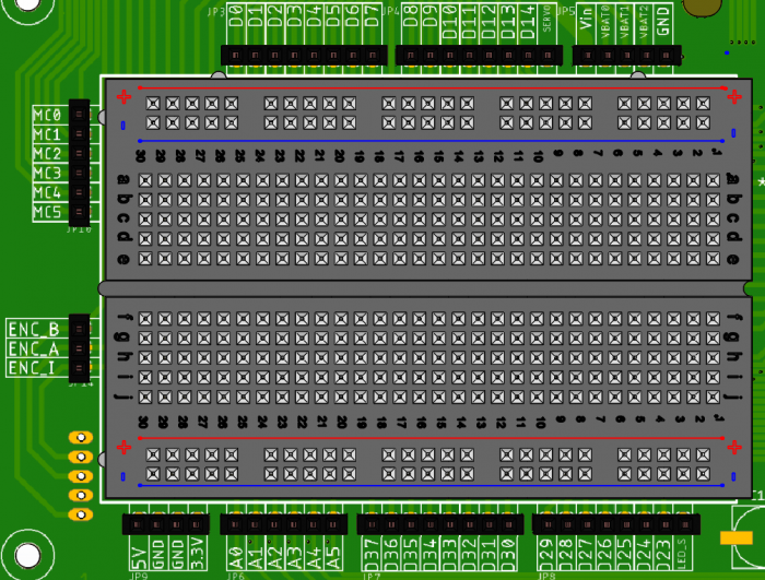
A breadboard is a device which can be used to quickly prototype custom electronics. The mainboard on the vehicle therefore has a breadboard. There are multiple headers placed on the sides of the breadboard. The different IOs on the OLIMEXINO and peripherals could be accessed through these headers. An image of the pinout is shown below.
Most of the headers are routed back to the OLIMEXINO. A couple of others are routed to different places on the mainboard. These are mainly placed on the left side of the breadboard. One of these headers goes towards a quadrature (rotary) encoder. This is the three pin female header with the following naming:
- ENC_B
- ENC_A
- ENC_I
This can be used to determine the speed of the vehicle. The other connector above starting with "MC0" is used in order to send signals to the motor driver. This will later be explained in another chapter.
The last connector on the top-right corner is dedicated to the power peripheral. This is connected to the LIPO battery. With this, it is possible to get access to the unregulated power of the LIPO battery. A couple of voltages that are accessible from here.
- Vin: 11.1V nominal
- VBAT0: Voltage accross the first cell in the LIPO battery
- VBAT1: Voltage accross the second cell in the LIPO battery
- VBAT2: Voltage accross the third cell in the LIPO battery
Prototyping board
A prototyping board, or perf board is used for prototyping electronic circuits. The mainboard also has headers specifically for the use of breadboards. The dimensions the mainboard is compatible with is : 5x7cm. See figure below for an example.
