Difference between revisions of "HANcoder/Training Material/SmartCar"
(→Prototyping board) |
(→Software) |
||
| Line 394: | Line 394: | ||
** Transmitting 'w' will cause the vehicle to move forward | ** Transmitting 'w' will cause the vehicle to move forward | ||
** Transmitting 's' will cause the vehicle to turn backwards | ** Transmitting 's' will cause the vehicle to turn backwards | ||
| + | |||
| + | = Theory of Operation = | ||
| + | |||
| + | == Bidirectional level shifting and input protection for digital signals == | ||
| + | |||
| + | == Input protection for analog signals == | ||
| + | |||
| + | == On-board 5V power == | ||
| + | |||
| + | == Current measuring == | ||
Revision as of 09:30, 15 February 2019
Contents
Introduction
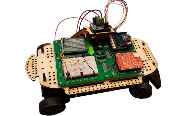
The smart car developed in part by HAN-AR is an all-in-one solution for beginner automotive students. It has built-in support for an OLIMEXINO-STM32, which utilizes a 32-bit microcontroller from STMicroelectronics. additionally, the platform has support for the following modules/features:
- Third party Arduino shields
- Third party motor drivers
- Inertial measurements unit (IMU)
- It has room for implementing your own electronics with a prototyping pcb (5*7cm) & breadboard
- Onboard speed sensor
- LIPO battery with an XT60 connector
- Current measurement functionality (±20A)
- Wireless emergency stop functionality
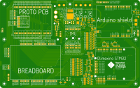
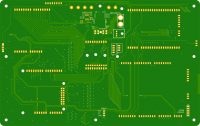
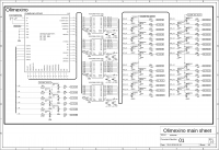
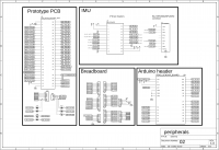
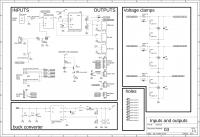
Schematic & Board images
EAGLE files, parts list
Eagle files: File:Eagle Smart Car PCB.zip
Parts list: File:Parts list.zip
Assembly Instructions
How to put the thing together
Mechanical construction
The vehicle’s base frame
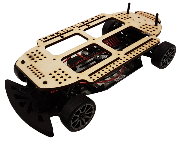
The vehicle consists of a basic frame that is manufactured by a company called “Reely”. This frame is pre-built and consists of the following components:
- The chassis containing
- Transmission
- Drive shaft
- Differential
- Suspension
The frame comes without a motor and wheels. Therefore, these components must also be included in the construction of the vehicle. The wheels and the motor are thus separately ordered. The motor type is a brushed DC motor instead of the brushless alternative. This is because brushless DC motors are easier to drive, as this can be done with an H-bridge circuit. The dimensions of the vehicle are as follows:
- Length : 365mm
- Width : 190mm
- Height : 122mm
- Wheelbase : 260mm
Mounting frame
The mounting frame is the frame on which the electronics can be fastened to. This mounting frame can be fastened to the vehicle via four posts. Under normal circumstances, these posts are used to mount a cover in order to style the vehicle. This is now retrofitted in order to fasten a plate to the vehicle. See the figure below.
The frame is made from 6mm thick birch plywood. Birch plywood has been chosen as the material because of the following reasons:
- It can easily be cut by a laser cutter
- It is cheap and widely available
- It is not brittle compared to other materials such as acrylic
Mainboard funtionalities
Olimexino support
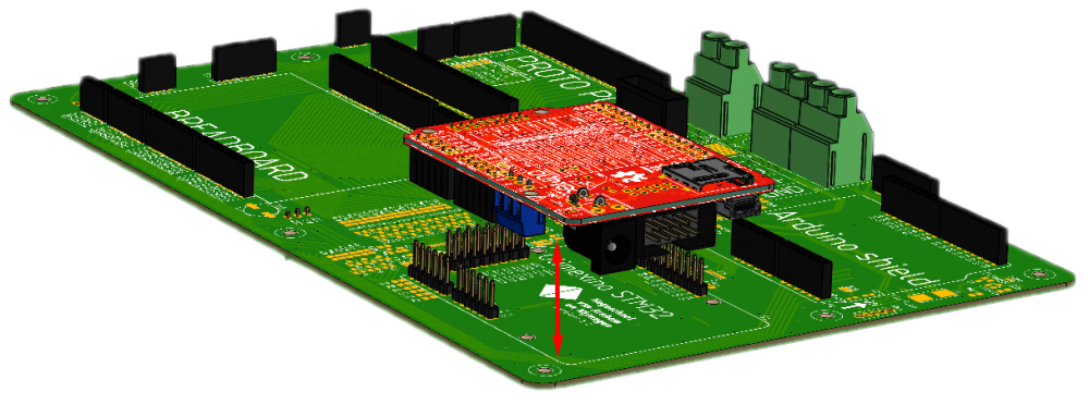
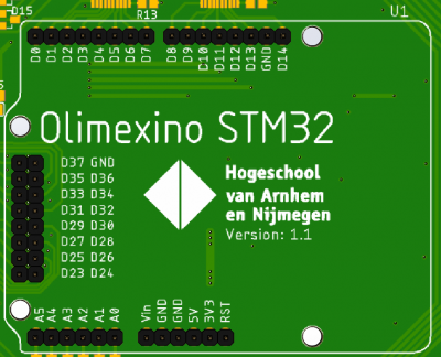
The OLIMEXINO-STM32 is a development board that houses a 32-bit microcontroller within. With the help of the OLIMEXINO-STM32, it is possible to control the vehicle's actions. The vehicle has a mainboard with built-in support for the OLIMEXINO-STM32. The OLIMEXINO can be fitted to a dedicated slot. See figure below.
There are several pins the user has access to when the OLIMEXINO-STM32 is utilized. The pins that are accessible are:
|
Third party Arduino shield support
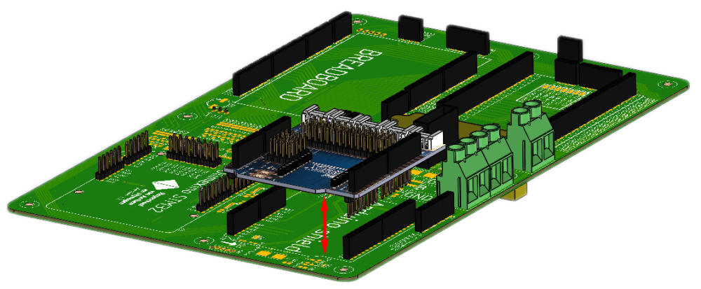
The mainboard on the vehicle has support for Arduino shields. Many different Arduino compatible shields can be fitted onto the mainboard in order to expand the functionality of the vehicle. A dedicated connector has been made to fit this purpose. See figure below.
For more information about third party Arduino shields, click here.
Inertial Measurement Unit
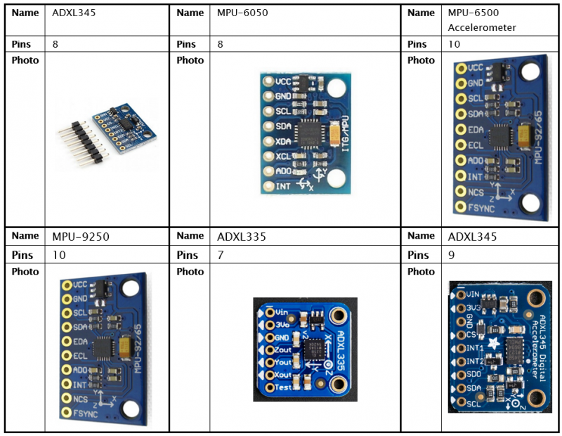
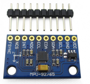
An IMU stands for Inertial Measurement Unit, which can be used for measuring a body’s forces. The mainboard is designed in such a way so that the IMU is interchangeable with other modules in order to keep the system flexible. There are many IMU modules available on the market. A small list of popular IMUs is shown below.
There are many more IMUs then are shown in the table above. Some IMUs have more features such as the ability to measure magnetic fields. Most use different ICs (Integrated Circuits), and depending on the IMU, it would also have a difference in communication protocols. This makes it so that the pinouts and even the physical sizes on many IMUs are different.
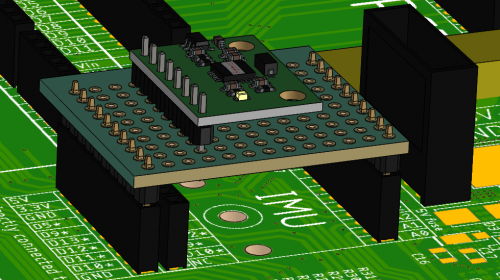
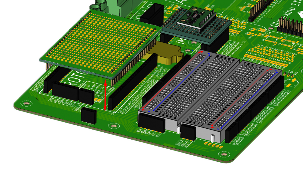
The mainboard has two methods of adding an IMU to the system. Method one consists of using a piece of prototyping board with two 10-pin male headers soldered on each side. The male headers interface with the two outer female headers that are present on the mainboard. By manually connecting each IO to the appropriate connector, it would be possible to connect a host of IMUs to the system. An example of how this would look like is shown in the figure below.
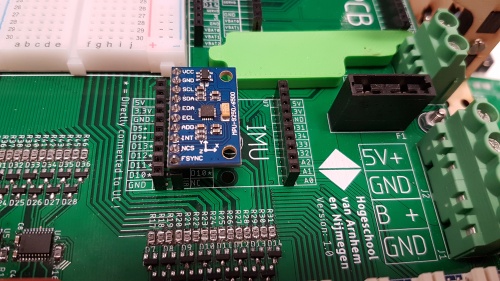
The second way of connecting an IMU to the system is by utilizing the middle connector on the mainboard. The IO on this connector is routed in order to be compatible to one IMU module. This bypasses the need to build a custom arrangement. The IMU module that is compatible is a generic board that uses a MPU-9250 IC. See the figures below for the implementation.
Adding custom electronics
Breadboard
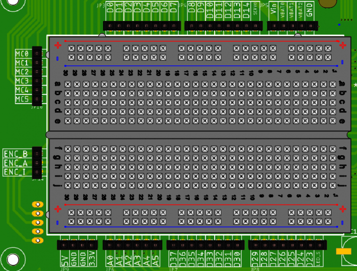
A breadboard is a device which can be used to quickly prototype custom electronics. The mainboard on the vehicle therefore has a breadboard. There are multiple headers placed on the sides of the breadboard. The different IOs on the OLIMEXINO and peripherals could be accessed through these headers. An image of the pinout is shown below.
Most of the headers are routed back to the OLIMEXINO. A couple of others are routed to different places on the mainboard. These are mainly placed on the left side of the breadboard. One of these headers goes towards a quadrature (rotary) encoder. This is the three pin female header with the following naming:
- ENC_B
- ENC_A
- ENC_I
This can be used to determine the speed of the vehicle. The other connector above starting with "MC0" is used in order to send signals to the motor driver. This will later be explained in another chapter.
The last connector on the top-right corner is dedicated to the power peripheral. This is connected to the LIPO battery. With this, it is possible to get access to the unregulated power of the LIPO battery. A couple of voltages that are accessible from here.
- Vin: 11.1V nominal
- VBAT0: Voltage accross the first cell in the LIPO battery
- VBAT1: Voltage accross the second cell in the LIPO battery
- VBAT2: Voltage accross the third cell in the LIPO battery
Prototyping board
A prototyping board, or perf board is used for prototyping electronic circuits. The mainboard also has headers specifically for the use of breadboards. The dimensions the mainboard is compatible with is : 5x7cm. See figure below for an example.
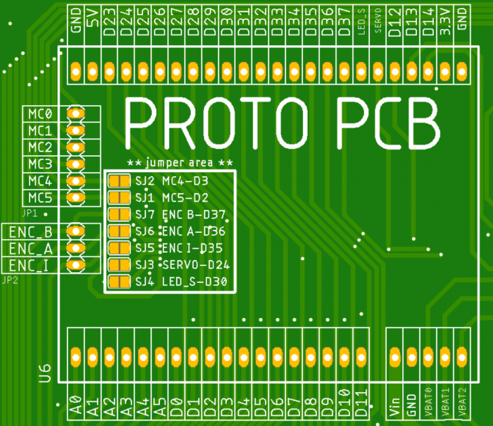
The pinout of the Proto PCB area:
Motor driver
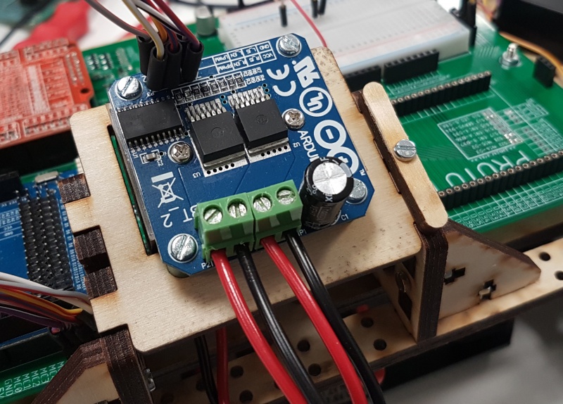
The mainboard doesn't have dedicated circuitry present to drive the motor of the vehicle. An external driver is therefore used to drive the vehicle's motor. The type of motor that is present on the vehicle is a brushed DC motor. This type of motor requires an H-bridge circuit in order to control the direction and speed of the motor. A recommended motor driver consists of two BTS7960B ICs that together comprise of a full H-bridge circuit. A prefabricated module is available that utilizes these ICs. This is shown in the figure below.
Be carefull in order to ensure that the module is wired correctly !
LIPO battery input & enabling the vehicle
Steering
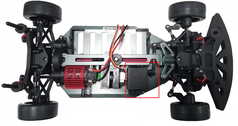
The component that is used for steering the vehicle is called a servo. The servo is a motor that is connected to an arm that can manipulate the steering angle of the two front wheels. The servo of the vehicle is shown in the figure below. The servo is encompassed by a red box.
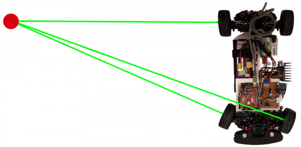
The steering mechanism itself follows the Ackermann steering geometry. The Ackermann steering geometry is a geometry that controls the angle of both wheels in such a way so that the tires don’t slip when the vehicle turns a corner. This is achieved by having a central point at which all tires rotate around. If you draw two lines perpendicularly through both wheels, then they will meet near or at the rear axle line. See Figure below for an illustration.
Servo motors are generally constructed using a train of reduction gears with a potentiometer connected to the output shaft. These features of a servo make it possible to precisely control the position of the output shaft, and thus precisely control the steering position. The positioning of the servo arm is measured with a potentiometer that is continually compared to the commanded position that is sent. The difference between the commanded position and the actual position generates an error signal which drives the motor either forwards or backwards. When the servo reaches the commanded position, then the error signal reduces and eventually becomes zero. The servo will then cease to move. The connection of an RC servo uses a standard 0.1” or 2.54mm spacing. The connector is usually a three pin Dupont female connector. An image of the connector of the servo is shown below.
The connector has three wires. The brown lead equals to the ground potential or 0V. The red lead is meant for the positive supply voltage. 5 Volts would normally be enough, but the datasheet of the servo motor contains the exact specifications. So, the datasheet must first be consulted before powering up the servo motor. The last lead is the orange wire. The orange wire controls the position of the servo. The way the positioning of the servo motor is controlled is through a process of varying a duty cycle of a square wave. Most generic microcontroller including the one present on the OLIMEXINO-STM32 support hardware based PWM signal generation. Click this link for more information. The connector for the servo can be hooked via the bottom of the mainboard. See figure below.
Wireless communication
Communication between the vehicle and a PC is crucial in order to receive live diagnostic data. The operator could receive data such as:
- Current speed
- Wheel angle
- IMU data
- Live voltage monitoring of the battery
- Get data from third-party sensors or modules
Other useful aspects for the operator is to adjust several parameters of the vehicle while it is in operation. The operator could, for example, tune Proportional Integral Differential (PID) control systems. The possibilities are up to the user or operator to decide. The vehicle would always stay within sight and indoors in normal circumstances. Therefore, distance of 10 meters is established as the minimum distance that the operator could still receive data from the vehicle. The data is transmitted by an Xbee module that is connected to an Arduino sensor shield. The individual components and the combined solution is shown in the figure below.
Two Xbee modules are necessary in order to establish communication between two systems. One Xbee module is connected to the host PC via USB and the other system is connected to the OLIMEXINO-STM32 on the miniature vehicle. See the figure below for the block diagram.
Both Xbee modules are programmed beforehand, so that only two modules can communicate with each other without interfering with other Xbees. Parameters such as the destination address, identifier, broadcasting modes (unicast & broadcast), transmission power and serial interfacing (baud rate, parity, stop bits) must all be set. See Programming the Xbee to see how to accomplish this.
Software
Programming the Xbee
[example 1] Testing the IO
[example 2] Wireless communication & driving the motor
Setting up the code w/ HANcoder
Global settings
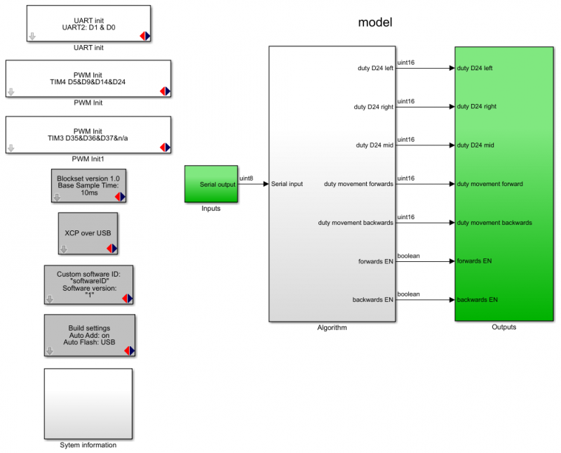
The vehicle's actions can be controlled with the OLIMEXINO-STM32. This chapter will discuss in detail how the vehicle could be set in motion, and how to communicate wirelessly with the vehicle. The image below shows the main view. First, the peripherals of the OLIMEXINO must be initialized. The vehicle utilizes three timers and the USART.
- The USART is used for communication purposes
- Three timers are used to control the vehicle's steering and forward/backward direction
- D24 is used for steering left or right
- D36 is used for moving the vehicle backwards
- D37 is used for moving the vehicle forwards
This will later be shown in detail. The figure below shows the global architecture.
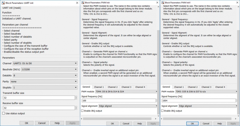
Configure the settings for the UART & PWM channels as follows:
- On the PWM block that has a frequency of 100Hz, enable channel 4 (D24)
- On the PWM block that has a frequency of 1004Hz, enable channel 2 & 3 (D36, D37)
Inputs
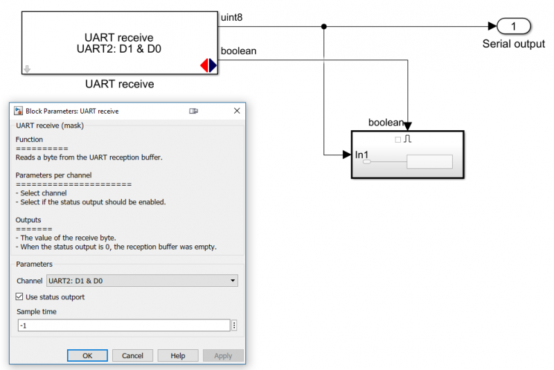
The vehicle receives data via the serial input. This therefore belongs at the input stage. This looks as shown below:
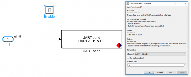
The subsystem (on the bottom right in the image above) sends the received data right back. It echo's the data back. This is done in order to test the functionality of the wireless transceiver. In order to duplicate the system, copy this as follows:
Algorithm
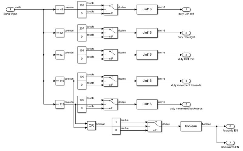
The algorithm processes the data that is received from the Xbee module. Depening on the input data, the vehicle would be able to perform different feats. See figure below.
First, the data is compared to a constant. This constant represents pressed keys on a keyboard following the ascii code. When for example a certain character is received, then the 8-bit code equals a value between 0 and 255. See http://www.asciitable.com/ to see which characters equals which integer value. If the received data equals the predetermined constant, then this will cause it to toggle a switch. The output of the switch will go towards a PWM peripheral on the microcontroller.
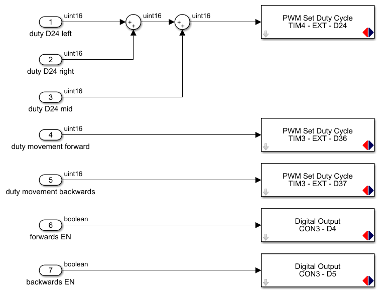
Outputs
The final part is the outputs. Here, all the signals will be ported through to the actual IO of the microcontroller. Copy it as shown below.
Testing the wireless communication
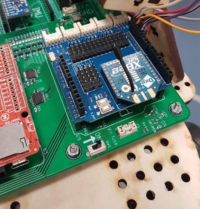
Connect a Sensor shield with an Xbee module attached to it to the mainboard of the vehicle. Make sure that the Xbee module is pre-programmed and pre-paired before doing so. See figure below:
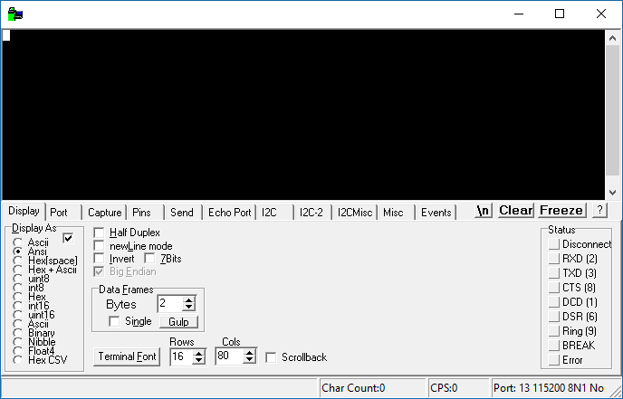
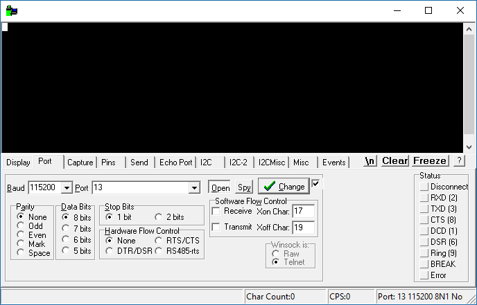
Connect a pre-programmed and pre-paired Xbee module to the computer. In order to communicate with the Xbee module that is connected to the computer, it is nescecarry to utilize a program that can send and transmit data with the correct protocol. A program called realterm is used to do this. It is also possible to do this with other software packages such as:
- Arduino IDE w/ a built-in COM terminal
- PuTTy
- Hyperterminal (windows xp)
Select Ansi in the Display As window
- Select the Baud to equal 115200
- Select the appropiate port on which the Xbee is connected to
- Click change
- Click Open
Enable the power on the vehicle. If you are a beginner, make sure nothing else on the vehicle is connected. Including the motor driver. That comes next !
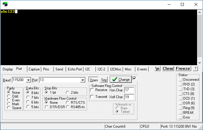
Click on the black area in the program and type in some characters. If you see the exact same characters appear on the main window, as you type them in, then it means that you succeeded with communicating with the vehicle.
Connecting the wires to the mainboard
Make sure that the power on the vehicle is not yet enabled !
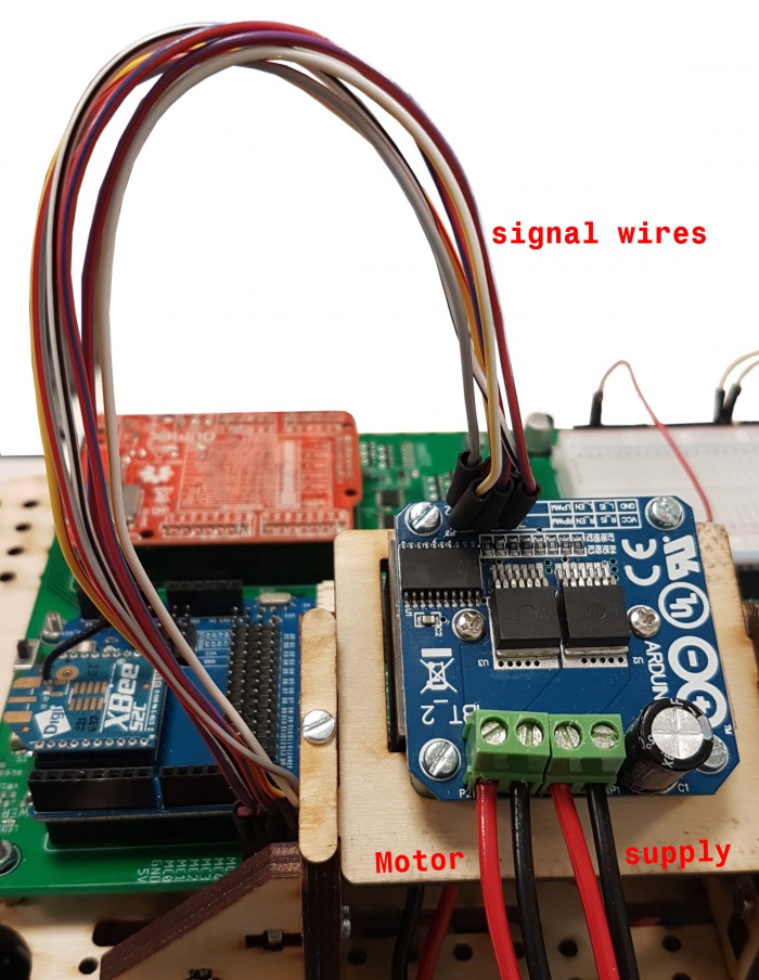
This example assumes that you are using the BTS7960B motor driver. Connect the motor and supply wires via the terminal blocks. Next, connect the following signal wires.
| BTS7960B | Mainboard |
| 5V | VCC |
| GND | GND |
| R_EN | MC0 |
| L_EN | MC1 |
| LPWM | MC2 |
| RPWM | MC3 |
Connecting the wires on the mainboard
Make sure that the power on the vehicle is not yet enabled !
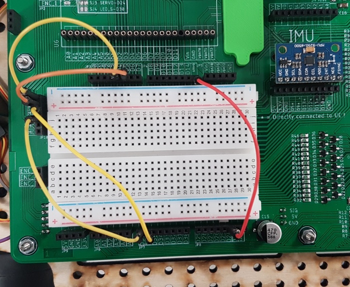
A couple of IOs were reserved for the purpose of controlling the vehicle. The following IOs will be utilized:
- D24 (steering)
- D36 (PWM forwards)
- D37 (PWM backwards)
- D4 (Enable)
- D5 (Enable)
The control signals of the motor driver is also connected to the mainboard via MC headers. These are:
- MC0 (R_EN)
- MC1 (L_EN)
- MC2 (LPWM)
- MC3 (RPWM)
Connect the relevant MC headers to the relevant IO of the OLIMEXINO. See figure below.
Powering up the vehicle and testing it
Make sure that the switch on the vehicle is in the OFF position. Enable it when instructed so.
If the OLIMEXINO has been flashed with the correct firmware, and if the wires on the vehicles has been connected. Then it can be tested. Perform the following steps:
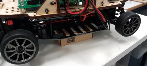
- Put something (e.g. a small box) between the chassis of the vehicle and the ground surface. So that the wheels do not contact the ground.
- Turn the vehicle on.
- On Realterm or other similar program, test if the vehicle will turn its wheels if you transmit '1', '2' or '3'.
- transmitting '1' will cause the vehicle to turn its wheels left
- transmitting '2' will cause the vehicle to turn its wheels to the center
- transmitting '3' will cause the vehicle to turn its wheels right
- Next, the motor can be controlled. Test if the vehicle will move forwards or backwards if you transmit 'w' or 's'.
- Transmitting 'w' will cause the vehicle to move forward
- Transmitting 's' will cause the vehicle to turn backwards
