Difference between revisions of "Parallel Hybrid Vehicle Simulation"
m (Willard de Jong moved page Parallel Hybrid vehicle simulation to Parallel Hybrid Vehicle Simulation) |
|||
| (137 intermediate revisions by 2 users not shown) | |||
| Line 1: | Line 1: | ||
| − | This | + | This page provides the steps on how to model a parallel hybrid vehicle, it has been documented in such a way that first time user can recreate the simulation from the beginning. <br/> |
| + | The reference result of this particular vehicle has been uploaded so that the user can compare their own simulation. <br/> | ||
| − | + | To learn more about how to create a simple model, go to [[SIMarchitect Tutorial]] | |
| − | |||
| − | |||
| − | |||
| − | |||
| − | |||
| − | |||
| + | == Creating the model== | ||
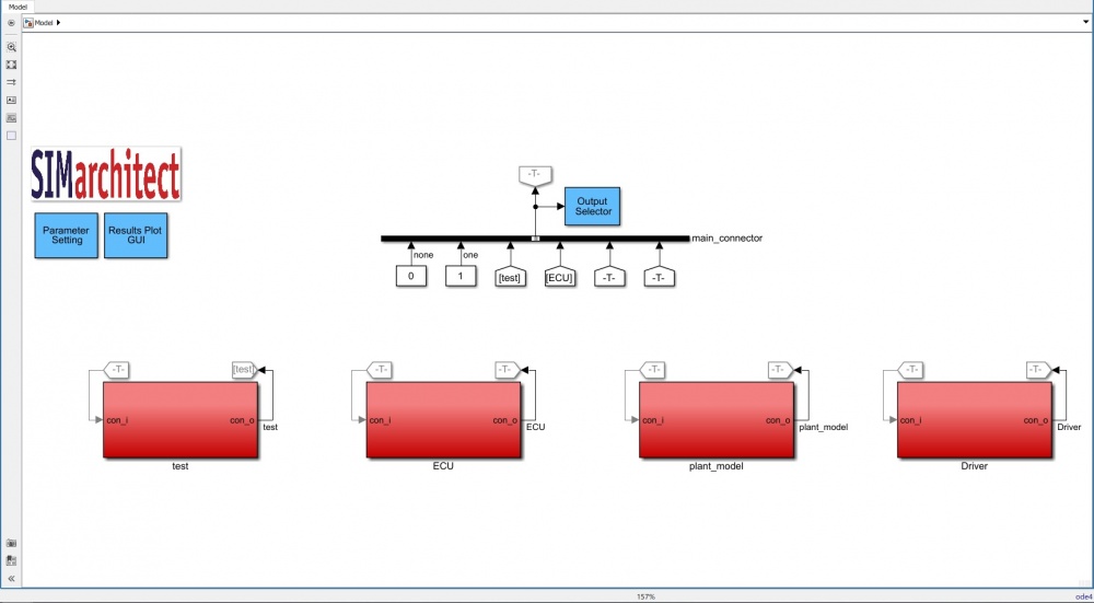
| + | The model is split into four different subsystems. Those are: | ||
| + | * Test scenario (Driving cycle) | ||
| + | * ECU | ||
| + | * Plant model (Parallel Hybrid vehicle powertrain component) | ||
| + | * Driver (Vehicle driver model) | ||
| − | + | [[File:Paralleladvsim.jpg|thumb|none|1000px|alt = none| Parallel Hybrid vehicle simulation]] | |
| − | [[File: | ||
| − | + | === Test Scenario === | |
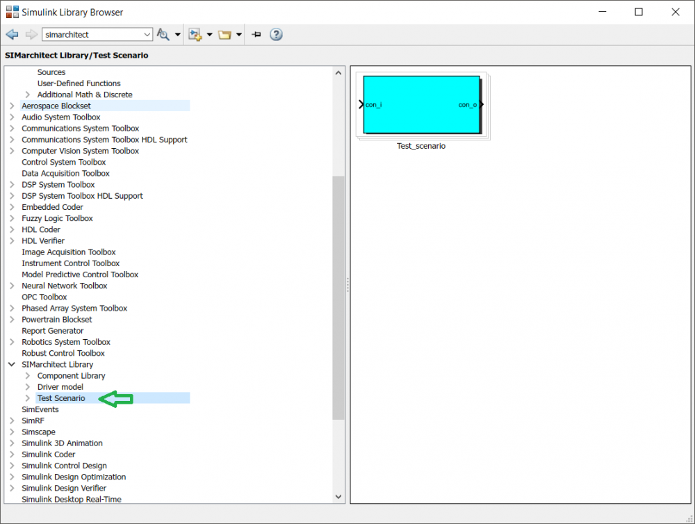
| − | [[File: | + | * Insert the '''Test_scenario''' component to (SIMarchitect) workspace, this component can be found under the Test Scenario in [[:File:SIMarchitect library.zip| SIMarchitect Library]]. |
| − | + | <br/> | |
| − | Do not | + | |
| + | [[File:Testscenario.png|thumb|none|1000px|alt = none| Test_scenario]] | ||
| + | |||
| + | === ECU === | ||
| + | To create the ECU subsystem: | ||
| + | * First insert an empty_area component to (SIMarchitect) workspace, this component can be found under the modeling tools below SIMarchitect general library <br/> | ||
| + | * Second, rename this empty_area componenent into '''ECU'''.<br/> | ||
| + | * Third, delete the in and out ports inside the '''ECU''' subsystem as it is shown in the figure below. | ||
| + | <br/> | ||
| + | [[File:emptyarea.jpg|thumb|none|1000px|alt = none| empty_area]] | ||
| + | <br/> | ||
| + | * Fourth, insert the ECU module to the '''ECU''' subsytem. The ECU module and its parameter file can be downloaded [[:File:Parallel hybrid vehicle simulation ECU.zip | here ]] | ||
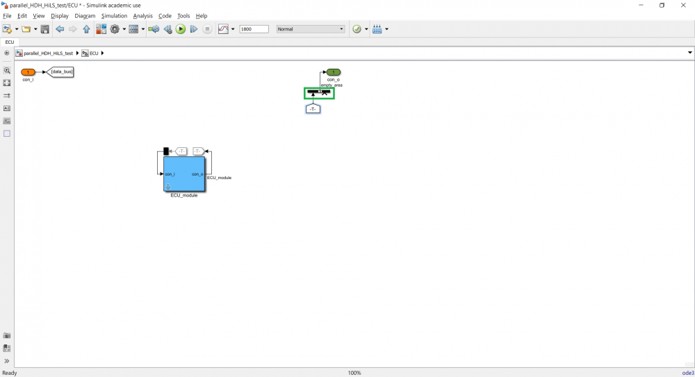
| + | *Fifth, delete the extra port in the sub_connector (green box in the figure below) by double-clicking the sub_connector and change the number of inputs into 1 to delete this extra port. | ||
| + | <br/> | ||
| + | [[File:ECUarea1.png|thumb|none|1000px|alt = none| ECU area]] | ||
| + | |||
| + | === Plant model === | ||
| + | To create the Plant_model subsystem: | ||
| + | * First insert an empty_area component to (SIMarchitect) workspace, this component can be found under the modeling tools below SIMarchitect general library. | ||
| + | * Second, rename this empty_area component into '''Plant_model'''. Do not use other names than the one specifies here otherwise, it will be confusing for assigning the signal input. | ||
| + | * Third, delete the in and out ports inside the '''Plant_model''' subsystem as it is shown in the empty_area figure above. | ||
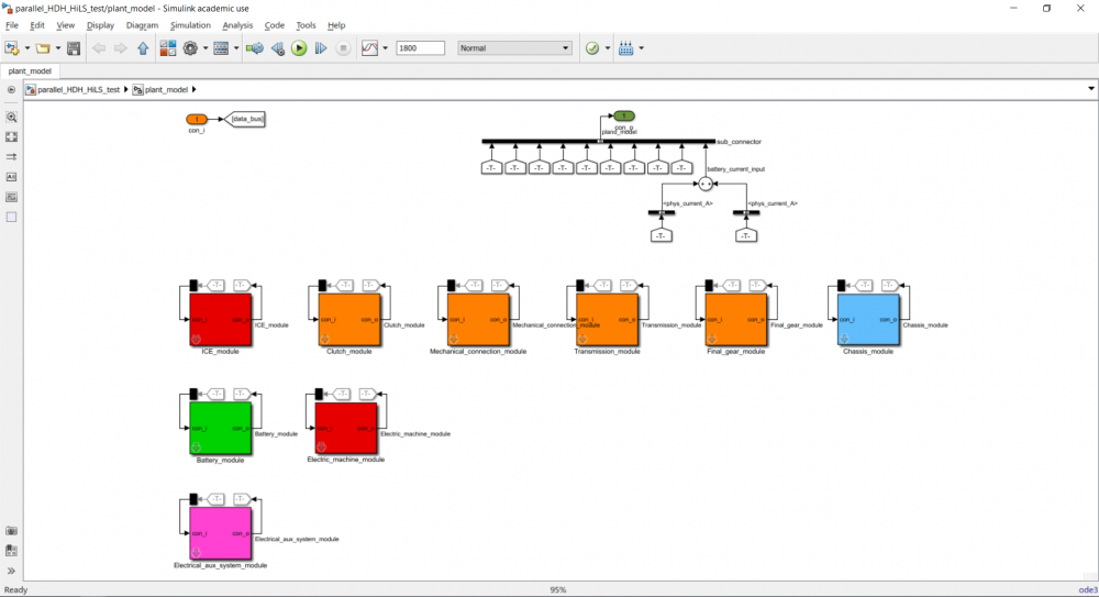
| + | * Fourth, insert the components listed below to the '''Plant_model''' subsystem and order them as it is shown in the figure below. | ||
| + | |||
| + | <br/> | ||
| + | |||
| + | All of the components can be found in the downloaded SIMarchitect library under component library → automotive → HDH - HiLS → chassis or powertrain and they are all color coded. | ||
| + | <br/> | ||
| + | |||
| + | The components of parallel hybrid vehicle powertrain: | ||
| + | * Internal Combustion Engine | ||
| + | * Clutch | ||
| + | * Mechanical connection | ||
| + | * Transmission | ||
| + | * Final gear | ||
| + | * Chassis | ||
| + | * Battery | ||
| + | * Electric machine | ||
| + | * Electrical auxiliary system | ||
| − | + | <br/> | |
| − | + | ||
| − | + | * Fifth, add an extra port in the sub_connector, this can be done by double-clicking the sub_connector and change the number of input to 10. | |
| + | * Sixth, locate the from tag of ''Electric machine module'' and ''Electrical auxiliary system'' and copy-paste it in the workspace. | ||
| + | * Seventh, insert two (2) Bus Selector(s) and connect it to each tag. | ||
| + | * Eighth, double-click the first bus selector, remove signal1 and signal2 under the selected signals inside the bus selector prompt and select ''Electric_machine_electrical_fb__output.phys_current_A'' under the ''Electric_machine_sensor''. | ||
| + | * Ninth, double-click the second bus selector, remove signal1 and signal2 under the selected signals inside the bus selector prompt and select ''Electrical_aux_electrical_fb_output.phys_current_A'' under the ''Electrical_aux_sensor''. | ||
| + | * Tenth, insert sum component to add the selected signals. | ||
| + | * Finally, connect the sum component to the sub_connector and rename the signal as battery_current_input. | ||
| + | |||
| + | <br/> | ||
| + | |||
| + | [[File:hybridparallelplantmodel.PNG|thumb|none|1000px|alt = none| Plant model area]] | ||
| + | |||
| + | === Driver === | ||
| + | To create driver subsystem: | ||
| + | * First insert an empty_area component to (SIMarchitect) workspace, this component can be found under the modeling tools below SIMarchitect general library. | ||
| + | * Second, rename this empty_area component into '''Driver'''. | ||
| + | * Third, delete the in and out ports inside the '''Driver''' subsystem as it is shown in the empty_area figure above. | ||
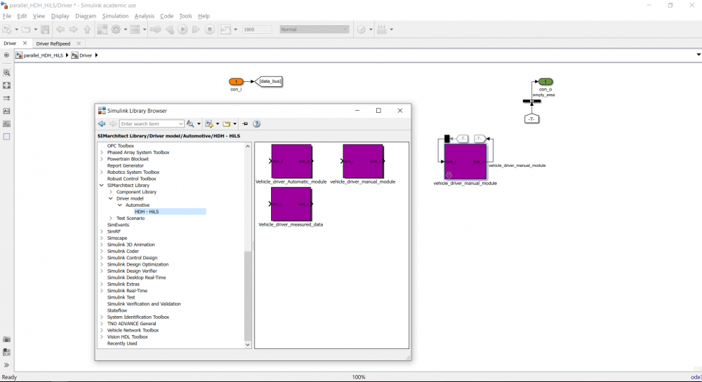
| + | * Fourth, insert the vehicle driver manual to the '''Driver''' subsystem. | ||
| + | * Fifth, delete the extra port in the sub_connector, by doing the same method as it was explained in the previous two subsystems. | ||
| + | [[File:driverarea1.png|thumb|none|1000px|alt = none| Driver area.]] | ||
| + | == Assigning signal inputs == | ||
=== ECU === | === ECU === | ||
| − | + | To assign the signal input for ECU module: | |
| − | + | * First, double-click the black box on top of the module to show the bus selector prompt. | |
| + | * Second, remove ''none'' from the selected signals area, located on the right-hand side of the bus selector prompt. | ||
| + | <br/> | ||
| + | Note: Be aware that the signal shown in the bus selector prompt might not be in the same order as it is shown in the table below. The signals should be assigned according to the order shown in the table below. Otherwise, the simulation will give an error and not run. | ||
| + | |||
| + | <br/> | ||
| − | |||
| − | |||
{| class="wikitable" | {| class="wikitable" | ||
|- | |- | ||
| − | |||
! Scope="col"| Input signal | ! Scope="col"| Input signal | ||
| + | ! colspan="2"| Located under | ||
! Scope="col"| Signal label | ! Scope="col"| Signal label | ||
| − | |||
|- | |- | ||
| − | |||
| Accelerator pedal position | | Accelerator pedal position | ||
| + | | rowspan="5" style="text-align: center;" | Driver | ||
| + | | rowspan="5" style="text-align: center;" | vehicle_driver_manual_module → Driver | ||
| ''Drv_AccPedl_Rt'' | | ''Drv_AccPedl_Rt'' | ||
| − | |||
|- | |- | ||
| Brake pedal position | | Brake pedal position | ||
| Line 53: | Line 112: | ||
| ''Drv_nrGearReq'' | | ''Drv_nrGearReq'' | ||
|- | |- | ||
| − | |||
| Actual engine speed | | Actual engine speed | ||
| + | | rowspan="22" style="text-align: center;" | Plant_model | ||
| + | | rowspan="4" style="text-align: center;" | ICE_module → ICE_sensor | ||
| ''Eng_nAct_radps'' | | ''Eng_nAct_radps'' | ||
| − | |||
|- | |- | ||
| Crankshaft torque | | Crankshaft torque | ||
| Line 68: | Line 127: | ||
|- | |- | ||
| Battery output current | | Battery output current | ||
| + | | rowspan="4" style="text-align: center;" | Battery_module → Battery_sensor | ||
| ''Batt_iAct_A'' | | ''Batt_iAct_A'' | ||
| − | |||
|- | |- | ||
| Battery output voltage | | Battery output voltage | ||
| Line 81: | Line 140: | ||
|- | |- | ||
| Clutch disengaged or not | | Clutch disengaged or not | ||
| + | | rowspan="1" style="text-align: center;" | Clutch_module → Clutch_sensor | ||
| ''Clu_flgConnected_B'' | | ''Clu_flgConnected_B'' | ||
| − | |||
|- | |- | ||
| Electric machine output torque | | Electric machine output torque | ||
| + | | rowspan="4" style="text-align: center;" | Electric_machine_module → Electric_machine_sensor | ||
| ''ElecMac_tqAct_Nm'' | | ''ElecMac_tqAct_Nm'' | ||
| − | |||
|- | |- | ||
| Electric machine output speed | | Electric machine output speed | ||
| Line 98: | Line 157: | ||
|- | |- | ||
| Transmission output speed | | Transmission output speed | ||
| + | | rowspan="4" style="text-align: center;" | Transmission_module → Transmission_sensor | ||
| ''Transm_nOutAct_radps'' | | ''Transm_nOutAct_radps'' | ||
| − | |||
|- | |- | ||
| Transmission gear number | | Transmission gear number | ||
| Line 111: | Line 170: | ||
|- | |- | ||
| Vehicle velocity | | Vehicle velocity | ||
| + | | rowspan="4" style="text-align: center;" | Chassis_module → Chassis_sensor | ||
| ''Chassis_vVehAct_mps'' | | ''Chassis_vVehAct_mps'' | ||
| − | |||
|- | |- | ||
| Wheel speed | | Wheel speed | ||
| Line 121: | Line 180: | ||
|- | |- | ||
| Road slope | | Road slope | ||
| − | | '' | + | | ''Chassis_slopeRoad_rad'' |
|- | |- | ||
| Auxiliary system output current | | Auxiliary system output current | ||
| + | | rowspan="1" style="text-align: center;" | Electrical_aux_system_module → Electrical_aux_sensor | ||
| ''Aux_iAct_A'' | | ''Aux_iAct_A'' | ||
| − | |||
|} | |} | ||
| + | |||
| + | <br/> | ||
=== Plant model === | === Plant model === | ||
| − | + | To assign the signal input for each component module: | |
| − | + | * First, double-click the black box on top of the module to show the bus selector prompt. | |
| + | * Second, remove ''none'' from the selected signals area, located on the right-hand side of the bus selector prompt. | ||
| + | * Third, follow the table below to assign signals to each component module. | ||
| + | <br/> | ||
| + | Note: Be aware that the signal shown in the bus selector prompt might not be in the same order as it is shown in the table below. <br/> | ||
| + | The signals should be assigned according to the order shown in the table below. Otherwise, the simulation will give an error and not run. | ||
<br/> | <br/> | ||
| − | |||
| − | |||
| − | |||
| − | |||
| − | |||
| − | |||
| − | |||
| − | |||
| − | |||
| − | |||
| − | |||
| − | + | '''ICE module''' | |
| + | |||
{| class="wikitable" | {| class="wikitable" | ||
|- | |- | ||
| − | |||
! Scope="col"| Input signal | ! Scope="col"| Input signal | ||
| + | ! colspan="2"| Located under | ||
! Scope="col"| Signal label | ! Scope="col"| Signal label | ||
| − | |||
|- | |- | ||
| − | |||
| Requested engine speed | | Requested engine speed | ||
| + | | rowspan="7" style="text-align: center;" | ECU | ||
| + | | rowspan="7" style="text-align: center;" | ECU_module → cmd | ||
| ''Eng_nReq_radps'' | | ''Eng_nReq_radps'' | ||
| − | |||
|- | |- | ||
| Switch Speed / torque control | | Switch Speed / torque control | ||
| Line 171: | Line 226: | ||
|- | |- | ||
| Starter motor ON / OFF | | Starter motor ON / OFF | ||
| − | | '' | + | | ''Eng_flgstrtrReq_B'' |
|- | |- | ||
| Fuel cut off | | Fuel cut off | ||
| Line 177: | Line 232: | ||
|- | |- | ||
| Engine rotational speed | | Engine rotational speed | ||
| + | | Plant_model | ||
| + | | rowspan="1" style="text-align: center;" | Clutch_module → clutch_mechanical_fb_output | ||
| ''phys_speed_radps'' | | ''phys_speed_radps'' | ||
| − | | | + | |} |
| + | |||
| + | <br/> | ||
| + | |||
| + | '''Clutch module''' | ||
| + | {| class="wikitable" | ||
| + | |- | ||
| + | ! Scope="col"| Input signal | ||
| + | ! colspan="2"| Located under | ||
| + | ! Scope="col"| Signal label | ||
|- | |- | ||
| − | |||
| Requested clutch pedal position | | Requested clutch pedal position | ||
| + | | rowspan="1" style="text-align: center;" | ECU | ||
| + | | rowspan="1" style="text-align: center;" | ECU_module → cmd | ||
| ''Clu_ratReq_B'' | | ''Clu_ratReq_B'' | ||
| − | |||
|- | |- | ||
| Clutch torque input | | Clutch torque input | ||
| + | | rowspan="3" style="text-align: center;" | plant_model | ||
| + | | rowspan="2" style="text-align: center;" | ICE_module → ICE_mechanical output | ||
| ''phys_torque_Nm'' | | ''phys_torque_Nm'' | ||
| − | |||
|- | |- | ||
| Clutch inertia input | | Clutch inertia input | ||
| Line 193: | Line 260: | ||
|- | |- | ||
| Clutch rotational speed input | | Clutch rotational speed input | ||
| + | | rowspan="1" style="text-align: center;" | Mechanical_connection_module → MC_mechanical_fb_output1 | ||
| ''phys_speed_radps'' | | ''phys_speed_radps'' | ||
| − | | | + | |} |
| + | |||
| + | <br/> | ||
| + | |||
| + | '''Mechanical connection module''' | ||
| + | {| class="wikitable" | ||
| + | |- | ||
| + | ! Scope="col"| Input signal | ||
| + | ! colspan="2"| Located under | ||
| + | ! Scope="col"| Signal label | ||
|- | |- | ||
| − | |||
| Mechanical connection torque input 1 | | Mechanical connection torque input 1 | ||
| + | | rowspan="5" style="text-align: center;" | plant_model | ||
| + | | rowspan="2" style="text-align: center;" | Clutch_module → clutch_mechanical_output | ||
| ''phys_torque_Nm'' | | ''phys_torque_Nm'' | ||
| − | |||
|- | |- | ||
| Mechanical connection inertia input 1 | | Mechanical connection inertia input 1 | ||
| Line 205: | Line 282: | ||
|- | |- | ||
| Mechanical connection torque input 2 | | Mechanical connection torque input 2 | ||
| + | | rowspan="2" style="text-align: center;" | Electric_machine_module → Electric_machine_mechanical_output | ||
| ''phys_torque_Nm'' | | ''phys_torque_Nm'' | ||
| − | |||
|- | |- | ||
| Mechanical connection inertia input 2 | | Mechanical connection inertia input 2 | ||
| Line 212: | Line 289: | ||
|- | |- | ||
| Mechanical connection feedback input | | Mechanical connection feedback input | ||
| + | | rowspan="1" style="text-align: center;" | Transmission_module → Transmission_mechanical_fb_output | ||
| ''phys_speed_radps'' | | ''phys_speed_radps'' | ||
| − | | | + | |} |
| + | |||
| + | <br/> | ||
| + | |||
| + | '''Transmission module''' | ||
| + | {| class="wikitable" | ||
| + | |- | ||
| + | ! Scope="col"| Input signal | ||
| + | ! colspan="2"| Located under | ||
| + | ! Scope="col"| Signal label | ||
|- | |- | ||
| − | |||
| Requested gear number | | Requested gear number | ||
| + | | rowspan="1" style="text-align: center;" | ECU | ||
| + | | rowspan="1" style="text-align: center;" | ECU_module → cmd | ||
| ''Transm_nrGearReq'' | | ''Transm_nrGearReq'' | ||
| − | |||
|- | |- | ||
| Transmission torque input | | Transmission torque input | ||
| + | | rowspan="3" style="text-align: center;" | plant_model | ||
| + | | rowspan="2" style="text-align: center;" | Mechanical_connection_module → MC_mechanical_output | ||
| ''phys_torque_Nm'' | | ''phys_torque_Nm'' | ||
| − | |||
|- | |- | ||
| Transmission inertia input | | Transmission inertia input | ||
| Line 228: | Line 316: | ||
|- | |- | ||
| Transmission rotational speed input | | Transmission rotational speed input | ||
| + | | rowspan="1" style="text-align: center;" | Final_gear_module → Final_gear_mechanical fb output | ||
| ''phys_speed_radps'' | | ''phys_speed_radps'' | ||
| − | | | + | |} |
| + | |||
| + | <br/> | ||
| + | |||
| + | '''Final gear module''' | ||
| + | {| class="wikitable" | ||
| + | |- | ||
| + | ! Scope="col"| Input signal | ||
| + | ! colspan="2"| Located under | ||
| + | ! Scope="col"| Signal label | ||
|- | |- | ||
| − | |||
| Final gear torque input | | Final gear torque input | ||
| + | | rowspan="3" style="text-align: center;" | plant_model | ||
| + | | rowspan="2" style="text-align: center;" | Transmission_module → Transmission_mechanical_output | ||
| ''phys_torque_Nm'' | | ''phys_torque_Nm'' | ||
| − | |||
|- | |- | ||
| Final gear inertia input | | Final gear inertia input | ||
| Line 240: | Line 338: | ||
|- | |- | ||
| Final gear rotational speed input | | Final gear rotational speed input | ||
| + | | rowspan="1" style="text-align: center;" | Chassis_module → Chassis_mechanical_fb_output | ||
| ''phys_speed_radps'' | | ''phys_speed_radps'' | ||
| − | | | + | |} |
| + | |||
| + | <br/> | ||
| + | |||
| + | '''Chassis module''' | ||
| + | {| class="wikitable" | ||
| + | |- | ||
| + | ! Scope="col"| Input signal | ||
| + | ! colspan="2"| Located under | ||
| + | ! Scope="col"| Signal label | ||
|- | |- | ||
| − | |||
| Requested chassis brake torque | | Requested chassis brake torque | ||
| + | | rowspan="1" style="text-align: center;" | ECU | ||
| + | | rowspan="1" style="text-align: center;" | ECU_module → cmd | ||
| ''Chassis_tqBrake_Nm'' | | ''Chassis_tqBrake_Nm'' | ||
| − | |||
|- | |- | ||
| Chassis torque input | | Chassis torque input | ||
| + | | rowspan="2" style="text-align: center;" | plant_model | ||
| + | | rowspan="2" style="text-align: center;" | Final_gear_module → Final_gear_mechanical_output | ||
| ''phys_torque_Nm'' | | ''phys_torque_Nm'' | ||
| − | |||
|- | |- | ||
| Chassis inertia input | | Chassis inertia input | ||
| Line 256: | Line 365: | ||
|- | |- | ||
| Drivecycle slope | | Drivecycle slope | ||
| − | | | + | | rowspan="1" style="text-align: center;" | Test_scenario |
| − | | rowspan="1" style="text-align: center;" | | + | | rowspan="1" style="text-align: center;" | Test_scenario |
| + | | ''drivecycle_time_slope'' | ||
| + | |} | ||
| + | |||
| + | <br/> | ||
| + | |||
| + | '''Battery module''' | ||
| + | {| class="wikitable" | ||
| + | |- | ||
| + | ! Scope="col"| Input signal | ||
| + | ! colspan="2"| Located under | ||
| + | ! Scope="col"| Signal label | ||
|- | |- | ||
| − | |||
| Battery current input | | Battery current input | ||
| − | | | + | | rowspan="1" style="text-align: center;" | plant_model |
| − | | rowspan="1" style="text-align: center;" | | + | | rowspan="1" style="text-align: center;" | plant_model |
| + | | ''battery_current_input'' | ||
|- | |- | ||
| Battery Actual cooling flow | | Battery Actual cooling flow | ||
| + | | rowspan="1" style="text-align: center;" | ECU | ||
| + | | rowspan="1" style="text-align: center;" | ECU_module → cmd | ||
| ''Batt_flowActCooling_kgps'' | | ''Batt_flowActCooling_kgps'' | ||
| − | | | + | |} |
| + | |||
| + | <br/> | ||
| + | |||
| + | '''Electric machine module''' | ||
| + | {| class="wikitable" | ||
| + | |- | ||
| + | ! Scope="col"| Input signal | ||
| + | ! colspan="2"| Located under | ||
| + | ! Scope="col"| Signal label | ||
|- | |- | ||
| − | |||
| Requested electric machine speed | | Requested electric machine speed | ||
| + | | rowspan="4" style="text-align: center;" | ECU | ||
| + | | rowspan="4" style="text-align: center;" | ECU_module → cmd | ||
| ''ElecMac_nReq_radps'' | | ''ElecMac_nReq_radps'' | ||
| − | |||
|- | |- | ||
| Switch speed / torque control | | Switch speed / torque control | ||
| Line 283: | Line 414: | ||
|- | |- | ||
| Electric machine voltage input | | Electric machine voltage input | ||
| + | | rowspan="2" style="text-align: center;" | plant_model | ||
| + | | rowspan="1" style="text-align: center;" | Battery_module → Battery_electrical output | ||
| ''phys_voltage_V'' | | ''phys_voltage_V'' | ||
| − | |||
|- | |- | ||
| Electric machine rotational speed input | | Electric machine rotational speed input | ||
| + | | rowspan="1" style="text-align: center;" | Mechanical_connection_module → MC_mechanical_join_output2 | ||
| ''phys_speed_radps'' | | ''phys_speed_radps'' | ||
| − | | | + | |} |
| + | |||
| + | <br/> | ||
| + | |||
| + | '''Electrical aux system module''' | ||
| + | |||
| + | {| class="wikitable" | ||
| + | |- | ||
| + | ! Scope="col"| Input signal | ||
| + | ! colspan="2"| Located under | ||
| + | ! Scope="col"| Signal label | ||
|- | |- | ||
| − | |||
| Requested power | | Requested power | ||
| + | | rowspan="1" style="text-align: center;" | ECU | ||
| + | | rowspan="1" style="text-align: center;" | ECU_module → cmd | ||
| ''Aux_pwrElecReq_W'' | | ''Aux_pwrElecReq_W'' | ||
| − | |||
|- | |- | ||
| Voltage input | | Voltage input | ||
| + | | rowspan="1" style="text-align: center;" | plant_model | ||
| + | | rowspan="1" style="text-align: center;" | Battery_module → Battery_electrical_output | ||
| ''phys_voltage_V'' | | ''phys_voltage_V'' | ||
| − | |||
|} | |} | ||
| − | + | <br/> | |
=== Driver === | === Driver === | ||
| − | + | To assign the signal input for Vehicle driver module: | |
| − | + | * First, double-click the black box on top of the module to show the bus selector prompt. | |
| + | * Second, remove ''none'' from the selected signals area, located on the right-hand side of the bus selector prompt. | ||
| + | * Third, follow the table below to assign signals to '''Vwhicle_driver_manual_module'''. | ||
| + | <br/> | ||
| + | Note: Be aware that the signal shown in the bus selector prompt might not be in the same order as it is shown in the table below. <br/> | ||
| + | The signals should be assigned according to the order shown in the table below. Otherwise, the simulation will give an error and not run. | ||
| + | |||
| + | <br/> | ||
| − | |||
{| class="wikitable" | {| class="wikitable" | ||
|- | |- | ||
| − | |||
! Scope="col"| Input signal | ! Scope="col"| Input signal | ||
| + | ! colspan="2"| Located under | ||
! Scope="col"| Signal label | ! Scope="col"| Signal label | ||
| − | |||
|- | |- | ||
| − | |||
| Actual vehicle velocity | | Actual vehicle velocity | ||
| + | | rowspan="4" style="text-align: center;" | plant_model | ||
| + | | rowspan="1" style="text-align: center;" | Chassis_module → Chassis_sensor | ||
| ''Chassis_vVehAct_mps'' | | ''Chassis_vVehAct_mps'' | ||
| − | |||
|- | |- | ||
| Transmission input speed | | Transmission input speed | ||
| + | | rowspan="2" style="text-align: center;" | Transmission_module → Transmission_sensor | ||
| ''Transm_nInAct_radps'' | | ''Transm_nInAct_radps'' | ||
| − | |||
|- | |- | ||
| Transmission actual gear number | | Transmission actual gear number | ||
| Line 327: | Line 476: | ||
|- | |- | ||
| Clutch disengaged or not | | Clutch disengaged or not | ||
| + | | rowspan="1" style="text-align: center;" | Clutch_module → clutch_sensor | ||
| ''Clu_flgConnected_B'' | | ''Clu_flgConnected_B'' | ||
| − | |||
|- | |- | ||
| + | | Accelerator pedal rate | ||
| rowspan="1" style="text-align: center;" | Driver | | rowspan="1" style="text-align: center;" | Driver | ||
| − | | | + | | rowspan="1" style="text-align: center;" | vehicle_driver_manual_module → Driver |
| ''Drv_AccPedl_Rt'' | | ''Drv_AccPedl_Rt'' | ||
| − | |||
|- | |- | ||
| − | |||
| Drive cycle time and speed | | Drive cycle time and speed | ||
| + | | rowspan="1" style="text-align: center;" | Test_scenario | ||
| + | | rowspan="1" style="text-align: center;" | Test_scenario | ||
| ''drivecycle_time_speed'' | | ''drivecycle_time_speed'' | ||
| − | |||
|} | |} | ||
== Simulation Settings == | == Simulation Settings == | ||
| − | There | + | There simulation settings for this simulation are: |
{| class="wikitable" | {| class="wikitable" | ||
! Scope="col" | Settings | ! Scope="col" | Settings | ||
| Line 357: | Line 506: | ||
|} | |} | ||
| − | The simulation | + | == Run the simulation == |
| + | To ensure that the simulation result of the created project is the same as the result shown in the next chapter, use this [[:File:Parallel hybrid vehicle simulation parameter file.zip | parallel hybrid vehicle parameter file]]. <br/> | ||
| + | |||
| + | Load the downloaded parameter into the created parallel hybrid vehicle simulation, this can be done by double-clicking the parameter setting button located on the top level layout of SIMarchitect and select the directory of where does the downloaded parameter file is located. | ||
| + | |||
| + | The sequence of running the simulation: | ||
| + | * First, run parameter_main m.file | ||
| + | * Second, choose the desired output results in the ''Output Selector'' block | ||
| + | * Third, run the simulation | ||
| + | * Fourth, plot the results using ''Results Plot GUI'' block | ||
The output from each individual module can be plotted using the ''Results Plot GUI''. | The output from each individual module can be plotted using the ''Results Plot GUI''. | ||
== Simulation Result == | == Simulation Result == | ||
| − | The simulation results of the parallel hybrid vehicle are as | + | Use these [[:File:Simulation Result.zip| Simulation Results]] to do graphical validation. <br/> |
| + | The simulation results of the parallel hybrid vehicle are as follows: | ||
{| class="wikitable" | {| class="wikitable" | ||
! Scope="col" | Module | ! Scope="col" | Module | ||
Latest revision as of 10:03, 13 August 2018
This page provides the steps on how to model a parallel hybrid vehicle, it has been documented in such a way that first time user can recreate the simulation from the beginning.
The reference result of this particular vehicle has been uploaded so that the user can compare their own simulation.
To learn more about how to create a simple model, go to SIMarchitect Tutorial
Contents
Creating the model
The model is split into four different subsystems. Those are:
- Test scenario (Driving cycle)
- ECU
- Plant model (Parallel Hybrid vehicle powertrain component)
- Driver (Vehicle driver model)
Test Scenario
- Insert the Test_scenario component to (SIMarchitect) workspace, this component can be found under the Test Scenario in SIMarchitect Library.
ECU
To create the ECU subsystem:
- First insert an empty_area component to (SIMarchitect) workspace, this component can be found under the modeling tools below SIMarchitect general library
- Second, rename this empty_area componenent into ECU.
- Third, delete the in and out ports inside the ECU subsystem as it is shown in the figure below.
- Fourth, insert the ECU module to the ECU subsytem. The ECU module and its parameter file can be downloaded here
- Fifth, delete the extra port in the sub_connector (green box in the figure below) by double-clicking the sub_connector and change the number of inputs into 1 to delete this extra port.
Plant model
To create the Plant_model subsystem:
- First insert an empty_area component to (SIMarchitect) workspace, this component can be found under the modeling tools below SIMarchitect general library.
- Second, rename this empty_area component into Plant_model. Do not use other names than the one specifies here otherwise, it will be confusing for assigning the signal input.
- Third, delete the in and out ports inside the Plant_model subsystem as it is shown in the empty_area figure above.
- Fourth, insert the components listed below to the Plant_model subsystem and order them as it is shown in the figure below.
All of the components can be found in the downloaded SIMarchitect library under component library → automotive → HDH - HiLS → chassis or powertrain and they are all color coded.
The components of parallel hybrid vehicle powertrain:
- Internal Combustion Engine
- Clutch
- Mechanical connection
- Transmission
- Final gear
- Chassis
- Battery
- Electric machine
- Electrical auxiliary system
- Fifth, add an extra port in the sub_connector, this can be done by double-clicking the sub_connector and change the number of input to 10.
- Sixth, locate the from tag of Electric machine module and Electrical auxiliary system and copy-paste it in the workspace.
- Seventh, insert two (2) Bus Selector(s) and connect it to each tag.
- Eighth, double-click the first bus selector, remove signal1 and signal2 under the selected signals inside the bus selector prompt and select Electric_machine_electrical_fb__output.phys_current_A under the Electric_machine_sensor.
- Ninth, double-click the second bus selector, remove signal1 and signal2 under the selected signals inside the bus selector prompt and select Electrical_aux_electrical_fb_output.phys_current_A under the Electrical_aux_sensor.
- Tenth, insert sum component to add the selected signals.
- Finally, connect the sum component to the sub_connector and rename the signal as battery_current_input.
Driver
To create driver subsystem:
- First insert an empty_area component to (SIMarchitect) workspace, this component can be found under the modeling tools below SIMarchitect general library.
- Second, rename this empty_area component into Driver.
- Third, delete the in and out ports inside the Driver subsystem as it is shown in the empty_area figure above.
- Fourth, insert the vehicle driver manual to the Driver subsystem.
- Fifth, delete the extra port in the sub_connector, by doing the same method as it was explained in the previous two subsystems.
Assigning signal inputs
ECU
To assign the signal input for ECU module:
- First, double-click the black box on top of the module to show the bus selector prompt.
- Second, remove none from the selected signals area, located on the right-hand side of the bus selector prompt.
Note: Be aware that the signal shown in the bus selector prompt might not be in the same order as it is shown in the table below. The signals should be assigned according to the order shown in the table below. Otherwise, the simulation will give an error and not run.
| Input signal | Located under | Signal label | |
|---|---|---|---|
| Accelerator pedal position | Driver | vehicle_driver_manual_module → Driver | Drv_AccPedl_Rt |
| Brake pedal position | Drv_BrkPedl_Rt | ||
| Drive cycle reference speed | Drivecycle_RefSpeed_mps | ||
| Clutch pedal position | Drv_CluPedl_Rt | ||
| Requested gear number | Drv_nrGearReq | ||
| Actual engine speed | Plant_model | ICE_module → ICE_sensor | Eng_nAct_radps |
| Crankshaft torque | Eng_tqCrkSftAct_Nm | ||
| Indicated torque | Eng_tqindAct_Nm | ||
| Engine oil temperature | Eng_tOilAct_K | ||
| Battery output current | Battery_module → Battery_sensor | Batt_iAct_A | |
| Battery output voltage | Batt_uAct_V | ||
| State of charge | Batt_socAct_Rt | ||
| Battery temperature | Batt_tAct_K | ||
| Clutch disengaged or not | Clutch_module → Clutch_sensor | Clu_flgConnected_B | |
| Electric machine output torque | Electric_machine_module → Electric_machine_sensor | ElecMac_tqAct_Nm | |
| Electric machine output speed | ElecMac_nAct_radps | ||
| Electric machine output current | ElecMac_iAct_A | ||
| Electric machine output temperature | ElecMac_tAct_K | ||
| Transmission output speed | Transmission_module → Transmission_sensor | Transm_nOutAct_radps | |
| Transmission gear number | Transm_nrGearAct | ||
| Clutch lock | Transm_flgConnected_B | ||
| Transmission input speed | Transm_nInAct_radps | ||
| Vehicle velocity | Chassis_module → Chassis_sensor | Chassis_vVehAct_mps | |
| Wheel speed | Chassis_nWheelAct_radps | ||
| Vehicle mass | Chassis_massVehAct_kg | ||
| Road slope | Chassis_slopeRoad_rad | ||
| Auxiliary system output current | Electrical_aux_system_module → Electrical_aux_sensor | Aux_iAct_A | |
Plant model
To assign the signal input for each component module:
- First, double-click the black box on top of the module to show the bus selector prompt.
- Second, remove none from the selected signals area, located on the right-hand side of the bus selector prompt.
- Third, follow the table below to assign signals to each component module.
Note: Be aware that the signal shown in the bus selector prompt might not be in the same order as it is shown in the table below.
The signals should be assigned according to the order shown in the table below. Otherwise, the simulation will give an error and not run.
ICE module
| Input signal | Located under | Signal label | |
|---|---|---|---|
| Requested engine speed | ECU | ECU_module → cmd | Eng_nReq_radps |
| Switch Speed / torque control | Eng_flgReqSwitch_B | ||
| Requested engine torque | Eng_tqReq_Nm | ||
| Exhaust brake ON / OFF | Eng_flgExhaustBrake_B | ||
| Engine ON / OFF | Eng_flgonoff_B | ||
| Starter motor ON / OFF | Eng_flgstrtrReq_B | ||
| Fuel cut off | Eng_flgFuelCut_B | ||
| Engine rotational speed | Plant_model | Clutch_module → clutch_mechanical_fb_output | phys_speed_radps |
Clutch module
| Input signal | Located under | Signal label | |
|---|---|---|---|
| Requested clutch pedal position | ECU | ECU_module → cmd | Clu_ratReq_B |
| Clutch torque input | plant_model | ICE_module → ICE_mechanical output | phys_torque_Nm |
| Clutch inertia input | phys_inertia_kgm2 | ||
| Clutch rotational speed input | Mechanical_connection_module → MC_mechanical_fb_output1 | phys_speed_radps | |
Mechanical connection module
| Input signal | Located under | Signal label | |
|---|---|---|---|
| Mechanical connection torque input 1 | plant_model | Clutch_module → clutch_mechanical_output | phys_torque_Nm |
| Mechanical connection inertia input 1 | phys_inertia_kgm2 | ||
| Mechanical connection torque input 2 | Electric_machine_module → Electric_machine_mechanical_output | phys_torque_Nm | |
| Mechanical connection inertia input 2 | phys_inertia_kgm2 | ||
| Mechanical connection feedback input | Transmission_module → Transmission_mechanical_fb_output | phys_speed_radps | |
Transmission module
| Input signal | Located under | Signal label | |
|---|---|---|---|
| Requested gear number | ECU | ECU_module → cmd | Transm_nrGearReq |
| Transmission torque input | plant_model | Mechanical_connection_module → MC_mechanical_output | phys_torque_Nm |
| Transmission inertia input | phys_inertia_kgm2 | ||
| Transmission rotational speed input | Final_gear_module → Final_gear_mechanical fb output | phys_speed_radps | |
Final gear module
| Input signal | Located under | Signal label | |
|---|---|---|---|
| Final gear torque input | plant_model | Transmission_module → Transmission_mechanical_output | phys_torque_Nm |
| Final gear inertia input | phys_inertia_kgm2 | ||
| Final gear rotational speed input | Chassis_module → Chassis_mechanical_fb_output | phys_speed_radps | |
Chassis module
| Input signal | Located under | Signal label | |
|---|---|---|---|
| Requested chassis brake torque | ECU | ECU_module → cmd | Chassis_tqBrake_Nm |
| Chassis torque input | plant_model | Final_gear_module → Final_gear_mechanical_output | phys_torque_Nm |
| Chassis inertia input | phys_inertia_kgm2 | ||
| Drivecycle slope | Test_scenario | Test_scenario | drivecycle_time_slope |
Battery module
| Input signal | Located under | Signal label | |
|---|---|---|---|
| Battery current input | plant_model | plant_model | battery_current_input |
| Battery Actual cooling flow | ECU | ECU_module → cmd | Batt_flowActCooling_kgps |
Electric machine module
| Input signal | Located under | Signal label | |
|---|---|---|---|
| Requested electric machine speed | ECU | ECU_module → cmd | ElecMac_nReq_radps |
| Switch speed / torque control | ElecMac_flgReqSwitch_B | ||
| Requested electric machine torque | ElecMac_tqReq_Nm | ||
| Electric machine actual cooling flow | ElecMac_flowActCooling_kgps | ||
| Electric machine voltage input | plant_model | Battery_module → Battery_electrical output | phys_voltage_V |
| Electric machine rotational speed input | Mechanical_connection_module → MC_mechanical_join_output2 | phys_speed_radps | |
Electrical aux system module
| Input signal | Located under | Signal label | |
|---|---|---|---|
| Requested power | ECU | ECU_module → cmd | Aux_pwrElecReq_W |
| Voltage input | plant_model | Battery_module → Battery_electrical_output | phys_voltage_V |
Driver
To assign the signal input for Vehicle driver module:
- First, double-click the black box on top of the module to show the bus selector prompt.
- Second, remove none from the selected signals area, located on the right-hand side of the bus selector prompt.
- Third, follow the table below to assign signals to Vwhicle_driver_manual_module.
Note: Be aware that the signal shown in the bus selector prompt might not be in the same order as it is shown in the table below.
The signals should be assigned according to the order shown in the table below. Otherwise, the simulation will give an error and not run.
| Input signal | Located under | Signal label | |
|---|---|---|---|
| Actual vehicle velocity | plant_model | Chassis_module → Chassis_sensor | Chassis_vVehAct_mps |
| Transmission input speed | Transmission_module → Transmission_sensor | Transm_nInAct_radps | |
| Transmission actual gear number | Transm_nrGearAct | ||
| Clutch disengaged or not | Clutch_module → clutch_sensor | Clu_flgConnected_B | |
| Accelerator pedal rate | Driver | vehicle_driver_manual_module → Driver | Drv_AccPedl_Rt |
| Drive cycle time and speed | Test_scenario | Test_scenario | drivecycle_time_speed |
Simulation Settings
There simulation settings for this simulation are:
| Settings | Value |
|---|---|
| Time | 1800 [s] |
| Fixed - step size | 0.01 |
| Solver type | ode3 (Bogacki - shampine) |
Run the simulation
To ensure that the simulation result of the created project is the same as the result shown in the next chapter, use this parallel hybrid vehicle parameter file.
Load the downloaded parameter into the created parallel hybrid vehicle simulation, this can be done by double-clicking the parameter setting button located on the top level layout of SIMarchitect and select the directory of where does the downloaded parameter file is located.
The sequence of running the simulation:
- First, run parameter_main m.file
- Second, choose the desired output results in the Output Selector block
- Third, run the simulation
- Fourth, plot the results using Results Plot GUI block
The output from each individual module can be plotted using the Results Plot GUI.
Simulation Result
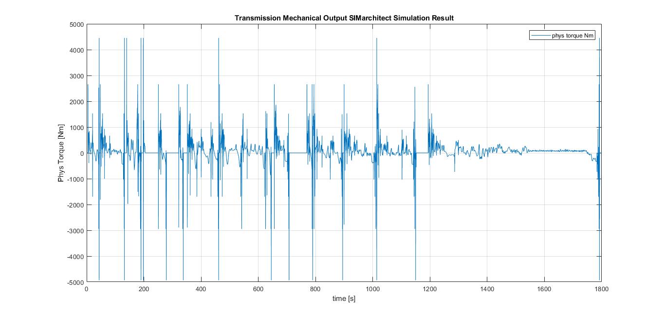
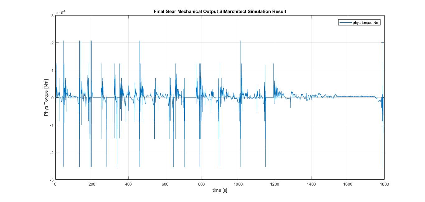
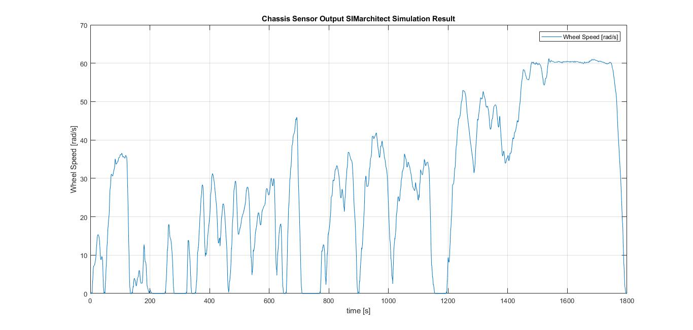
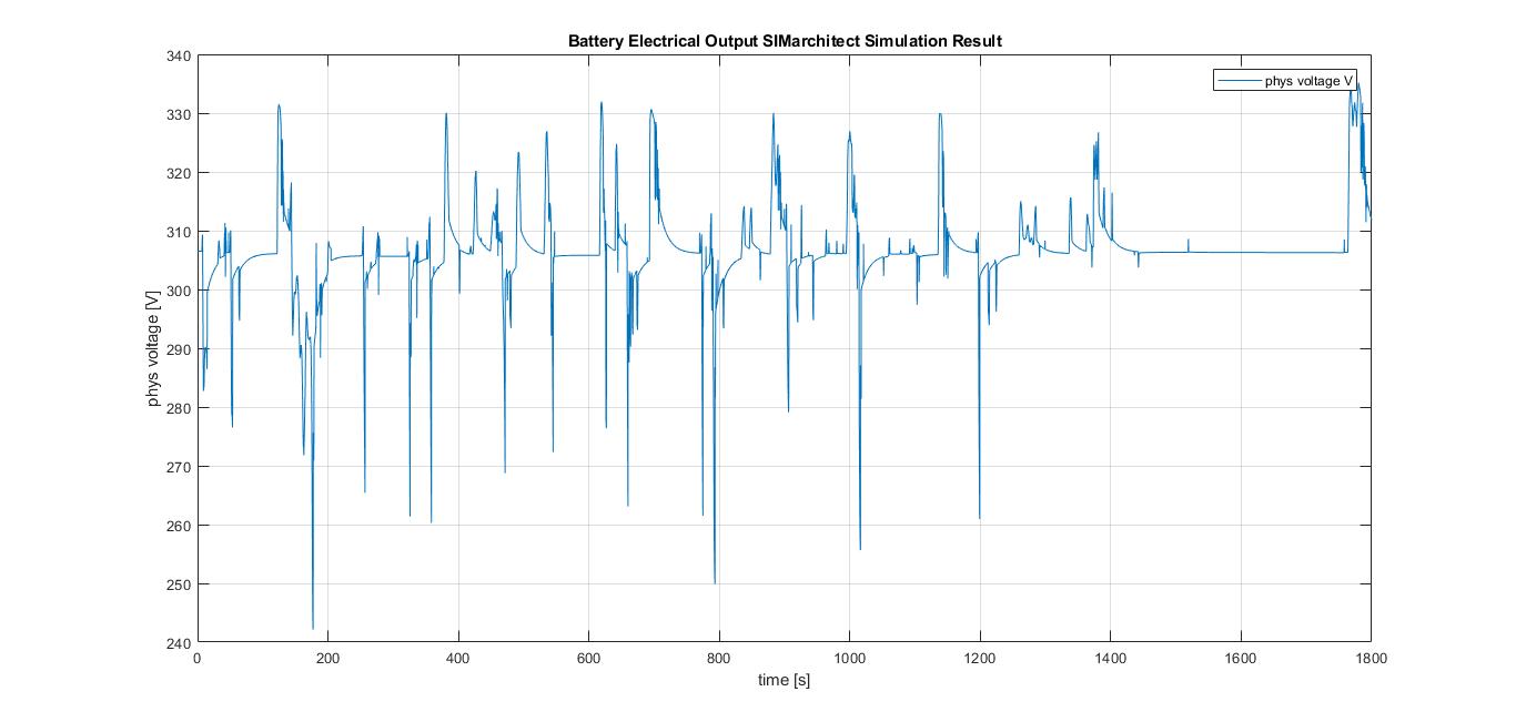
Use these Simulation Results to do graphical validation.
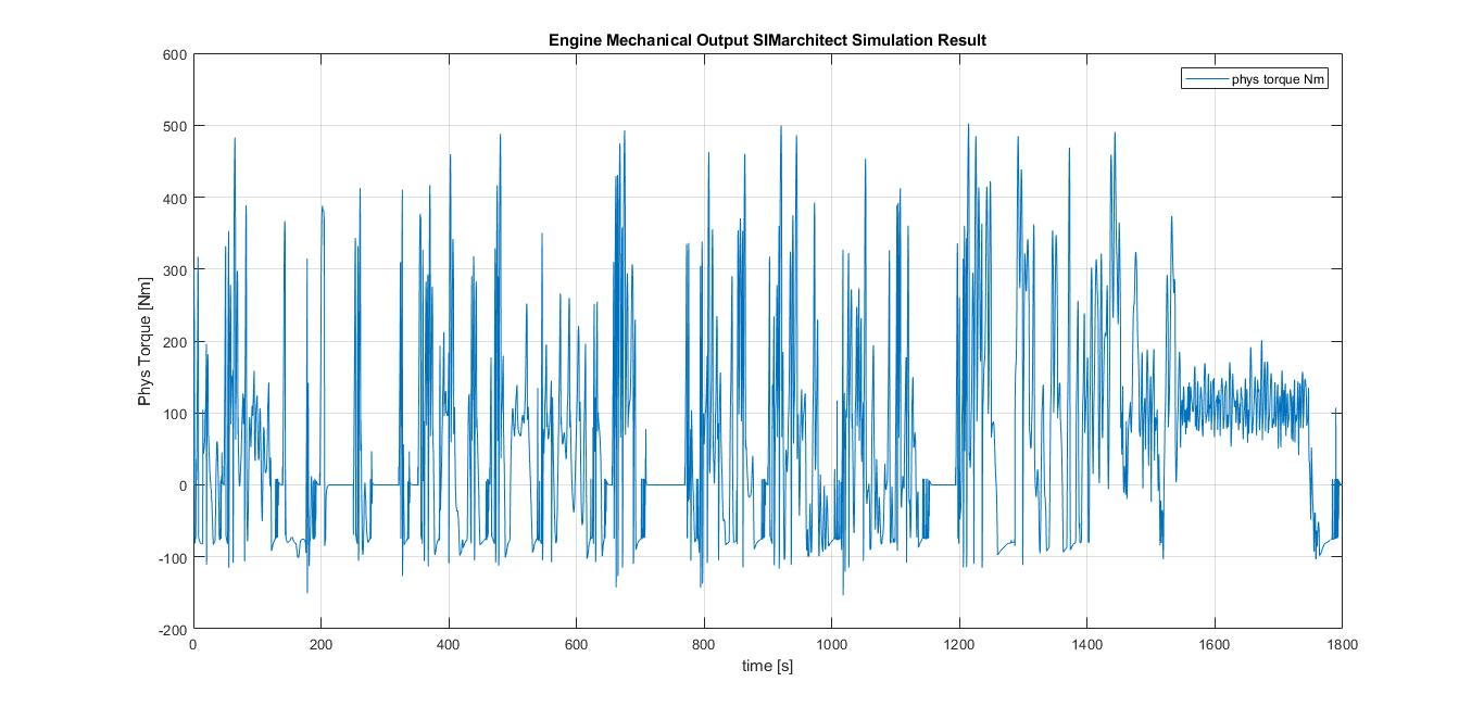
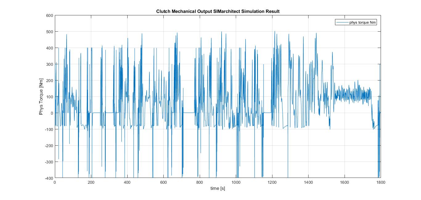
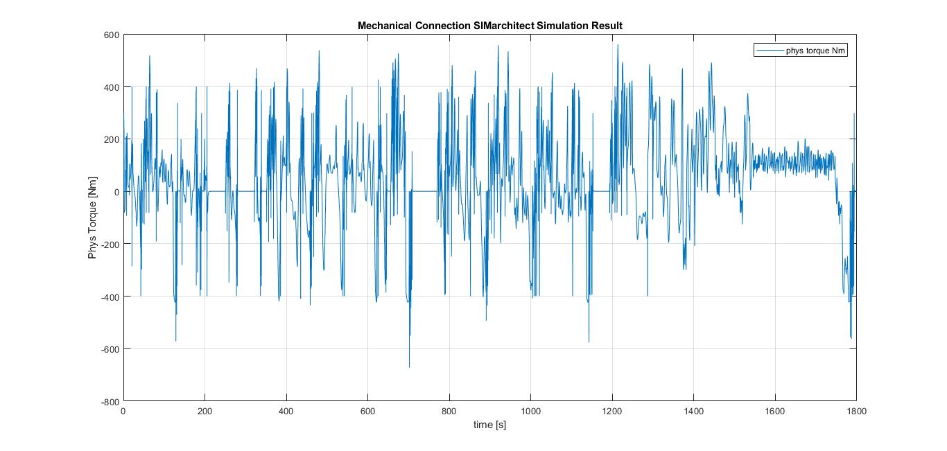
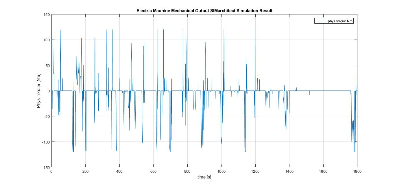
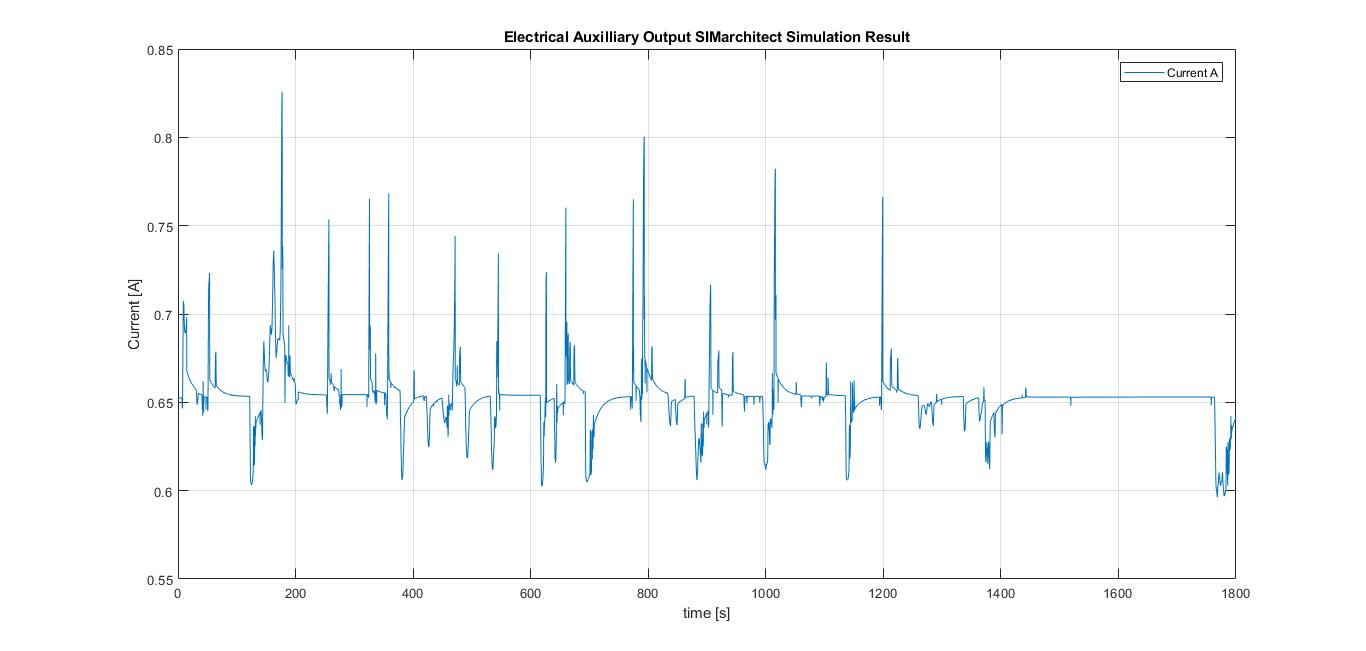
The simulation results of the parallel hybrid vehicle are as follows:
| Module | Result |
|---|---|
| Internal Combustion Engine | |
| Clutch | |
| Mechanical connection | |
| Transmission | |
| Final gear | |
| Chassis | |
| Battery | |
| Electric Machine | |
| Electrical Auxiliary system |
