HANcoder/Training Material/AutomaticLightControlSystem/2
Contents
LED Control System Part 2
Part 2: Adding analog signals and making them visible in HANtune
Introduction to Simulink
You will be introduced to a program called Simulink. Simulink will be the environment that we’ll use to develop the models. Firstly, you’ll need to open the model template. This model template can be found in the following directory: HANcoder\Target\HANcoder_Olimexino.slx
Adding an analog input to the model
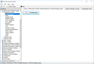
The goal of this first part of the tutorial is to read the input of a potentiometer that’s been connected to the sensor shield. As you can see, the sensor shield has been connected to analog input A0. By simply adding the Analog Input block from the library, the Olimexino will be able to read an analog signal from a potentiometer, for example. Open Simulink, click “Library Browser” and navigate to HANcoder STM32 Target => Olimexino STM32 => Analog Inputs. In the right column, the Analog Input block will appear. Select the block and drag it into the template model.
Figure 1 Library Browser Analog Input
Making the signals visible in HANtune
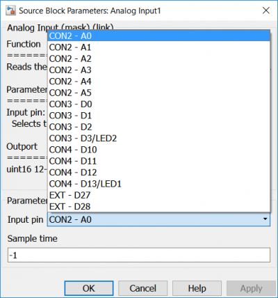
Configure the Analog Input block to read the Input pin A0 by double clicking it. We want to read the output of the Analog Input block in HANtune.
Figure 2 Analog Input Block Parameters
Tip: Always be sure to read the description of the function block thoroughly. This description contains information about its function, the adjustable parameters and the input and output signals.
Because the signal won’t be used for a control system, it needs to be terminated with a terminator, which can be found in the Library Browser as well. You’ll find that the terminator block will be used quite frequently. Therefor it can be found in the library browser under Simulink => Commonly Used Blocks. Connect the Analog Input block to the Terminator block.
Figure 3 Analog Input without signal description
We want to be able to read the signal from A0 in HANtune. In order to do that, we need to ensure that it’s available as a signal within HANtune. The first thing we’ll need to do, is naming the signal logically. To name a signal, double click the line. A text box should appear beneath the line. Name it sensibly, for example: Potmeter_out.
Figure 4 Analog Input with signal description
When you build a model, two important files will be created: an S record file (.srec) and an ASAP2 file (.a2l).
The S record file contains the compiled model. It contains the machine code that is used to program the microcontroller.
The ASAP2 file has information about the model with, amongst other things, signals that we want to view in HANtune. HANtune needs this file to know which parameters are available in the microcontroller to read or change.
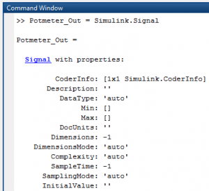
To make a signal or parameter visible in HANtune , you’ll need to add this signal to the ASAP2 file. This is done with the MATLAB® Command Window. For this you need to open the program “MATLAB®”. The MATLAB® Command Window can be found at the bottom of the screen. To add the signal to the ASAP2 file by typing the following command: Potmeter_Out = Simulink.Signal
Now a signal called “Potmeter_Out” should be visible in the Workspace, which can be found at the right side of the MATLAB® window.
Figure 5 MATLAB® Command Window (add Signal)
To make the signal usable for HANtune, the Storage class property needs to be change. This can be done by double clicking the Potmeter_Out signal in the Workspace. When the property window appears, you’ll need to change the Storage Class to ExportedGlobal. This will add the signal to the ASAP2 file for HANtune to read.
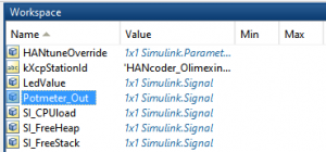 Figure 6 Added signal visible in Workspace
 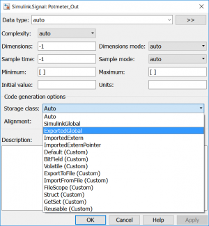 Figure 7 Change Signal to Exported Global
